|
In this website, using M.O.B 3D Printer as an example, we will show you the basic set up necessary.
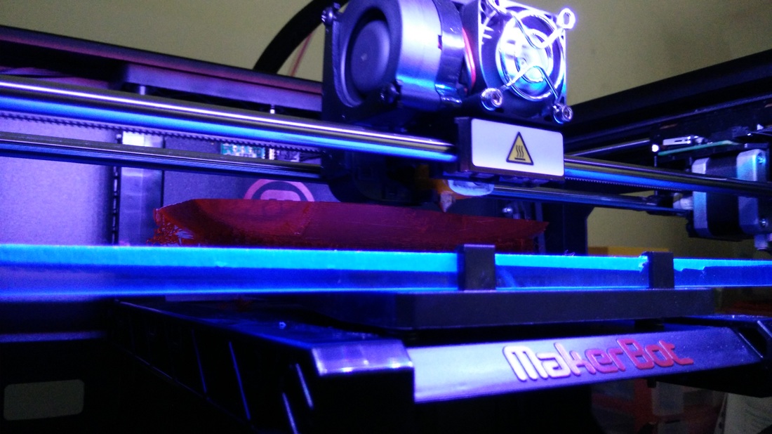
Note that most prints shown in this website were created by M.O.B 3D Printer and MakerBot Replicator.
DownloadsNote that different printers require different software, so do check with your supplier if you are unsure.
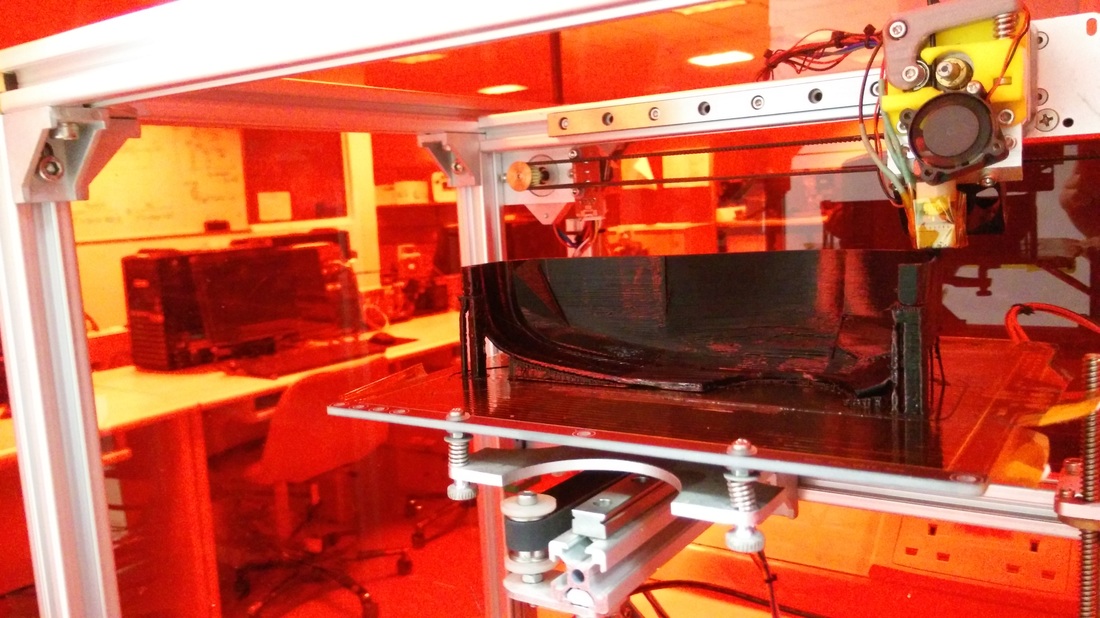
M.O.B 3D Printer
Pronterface is used to control the printer and printing models.
The file below is obtained from Romscraj on how to set up. This website however will provide you a pictorial guide.
Alternatively, if you use MakerBot Replicator, you can control the printer from the interface on the printer itself. Makebot Desktop is used for slicing models.
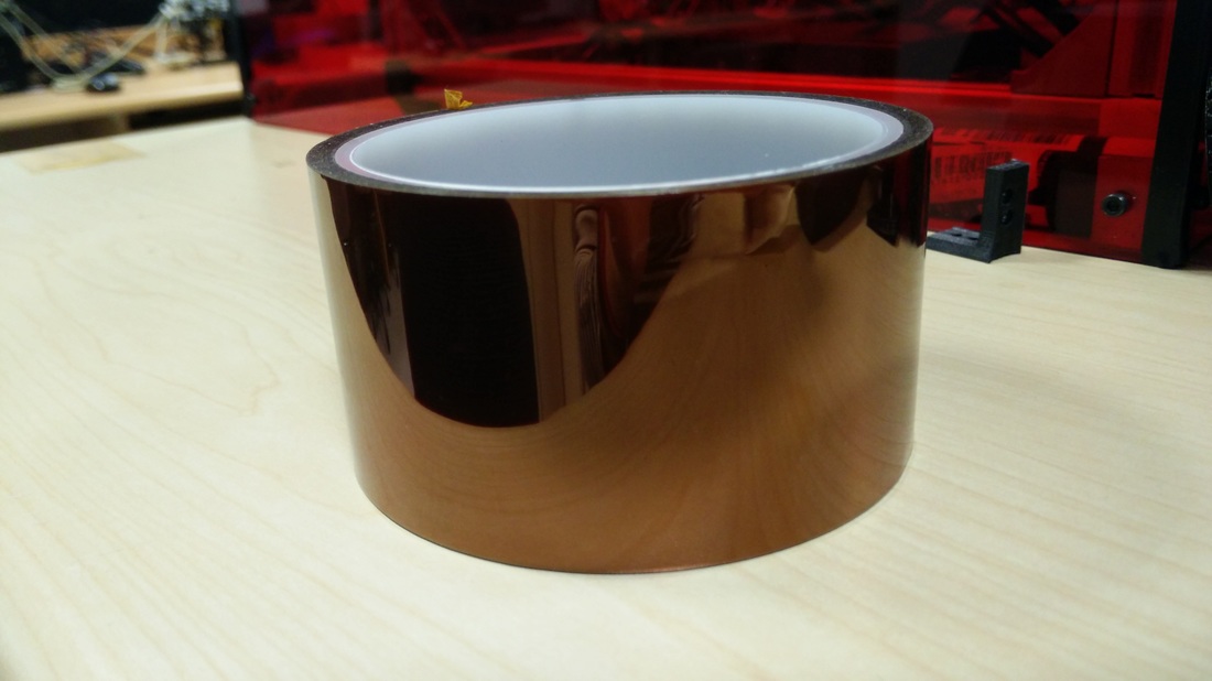
Step 1Layer your heat bed with Kapton tape or other 3D printing tape (such as Blue Painter's tape).
Wipe the heat bed if necessary before placing the tape. There should also be no air bubbles to ensure that the the surface is smooth. Try using a plastic card to help smooth out the air bubbles.
STEP 2Go to Settings, the Options and configure accordingly.
Connect USB of M.O.B 3D Printer to laptop or PC.
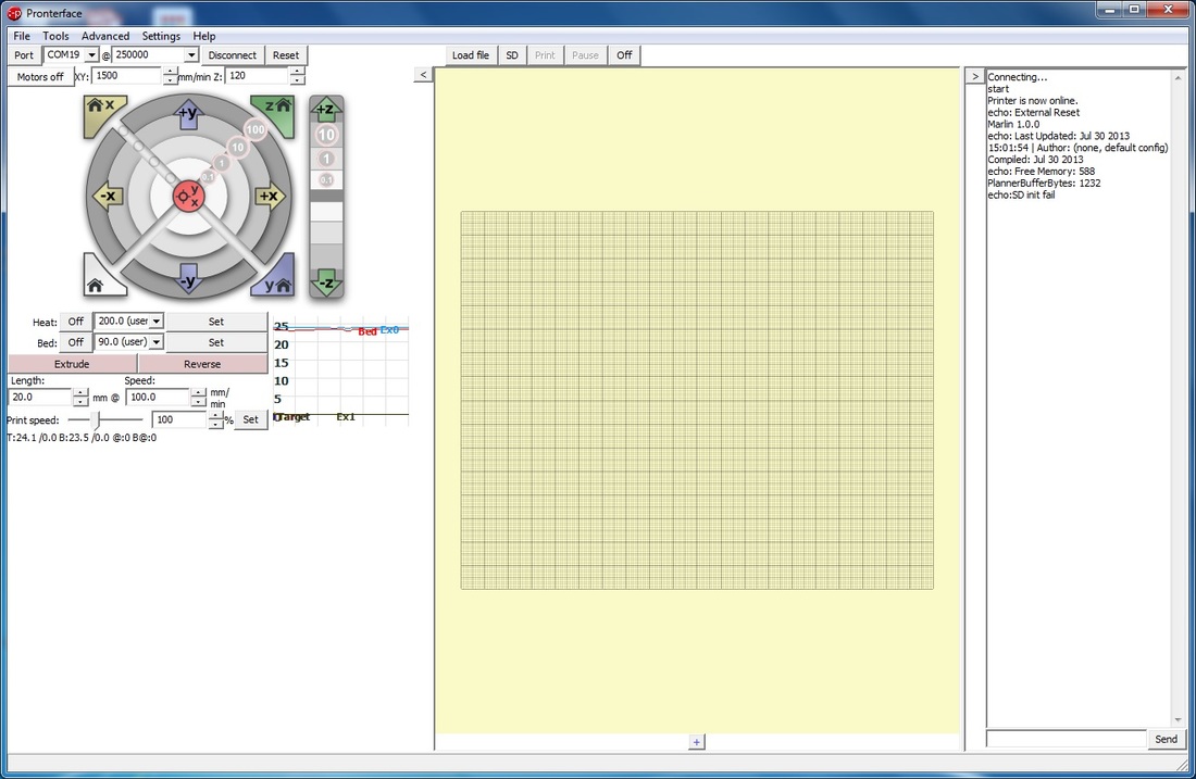
Launch Pronterface. Select the respective port (here it is COM19), baud rate of 250000 and select Connect.
Once connected, observe in the right panel that you are able to start. Relevant information on the printer will also be displayed. If no SD card is present, it will show SD init fail.
You may follow the settings shown below if you are using the PLA filament of 1.75mm.
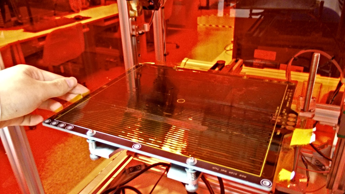
step 3Before heating up the nozzle or bed, ensure that the heatbed is balanced.
Press the home button. 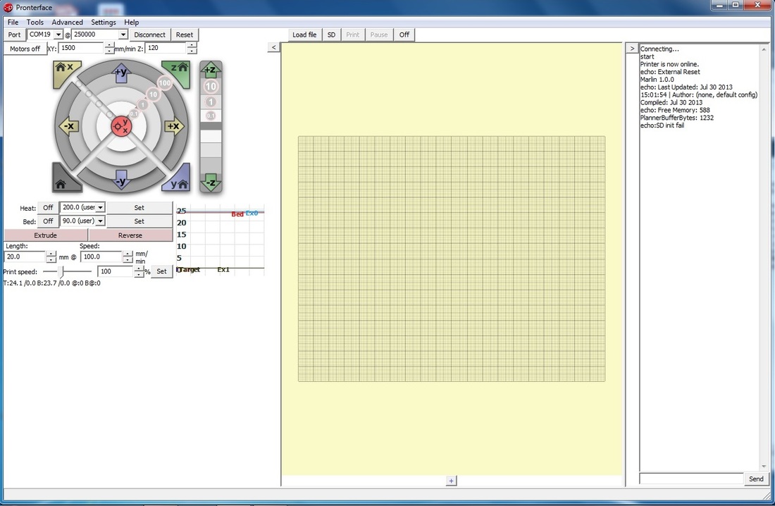
The extruder will move to the left hand bottom corner (depending on how you orientate your printer). Place a small piece of paper between the tip and the bed.
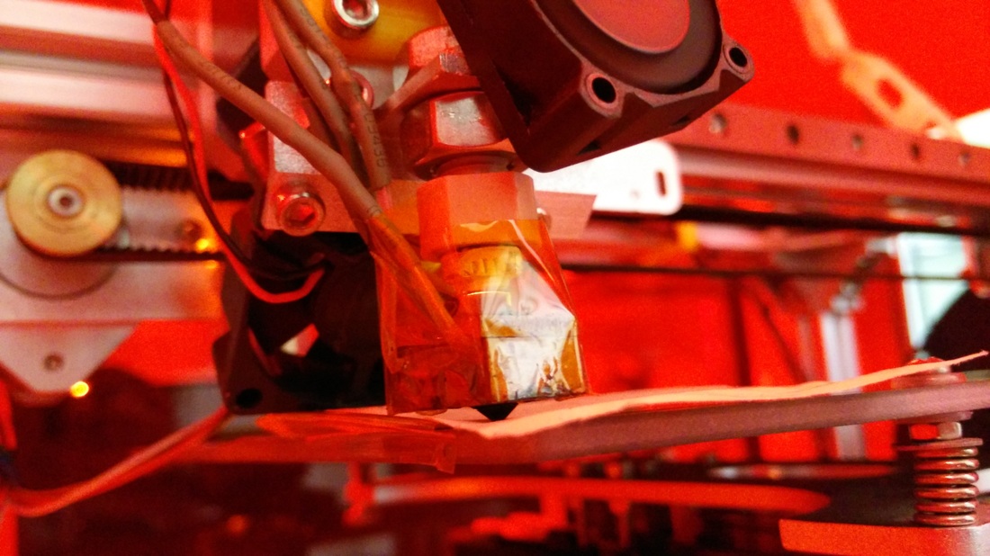
Adjust the screw until the paper is removed not too easily nor with too much force (somewhere in between). You should be able to pull the paper out without much force and feeling the tip scraping against it.
Try repeating a few times so that you remember how secure it feels (roughly) as you will need to repeat the same action for the remaining 3 corners. Next, move the nozzle to the opposite corner. Lift the nozzle using +Z (either 0.1, 1 or 10, depending on how high you prefer to lift it). 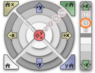
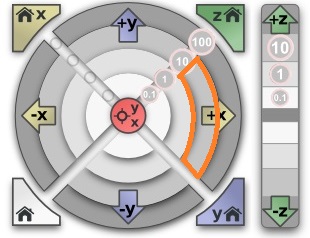
You can then move it along the X-axis using the +X buttons (either 0.1, 1 or 10).
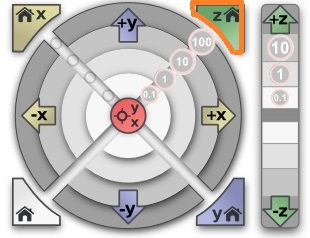
Once the nozzle reaches close to the end of the X-axis (but within the white box drawn on the heatbed), select the Z-home button. This will allow the nozzle to touch the heatbed again. Repeat the similar procedure by placing a paper and tightening/loosening the screws accordingly.
Once done, lift the nozzle tip again using the +Z buttons. This time, move along the Y-axis.
Repeat the procedure of placing the paper and screwing the heat bed accordingly.
Remember to lift the nozzle again before moving to the last corner. Using the +/- buttons for X and Y, select Z home button and move the nozzle tip diagonally across (and around) the heat bed. Ensure that it does not scratch the heat bed at any point.
STEP 4Launch Slic3r application (it can be found within the Pronterface file, you may choose to place a shortcut for it on the desktop as well). Select the relevant settings.
Select "Add...".
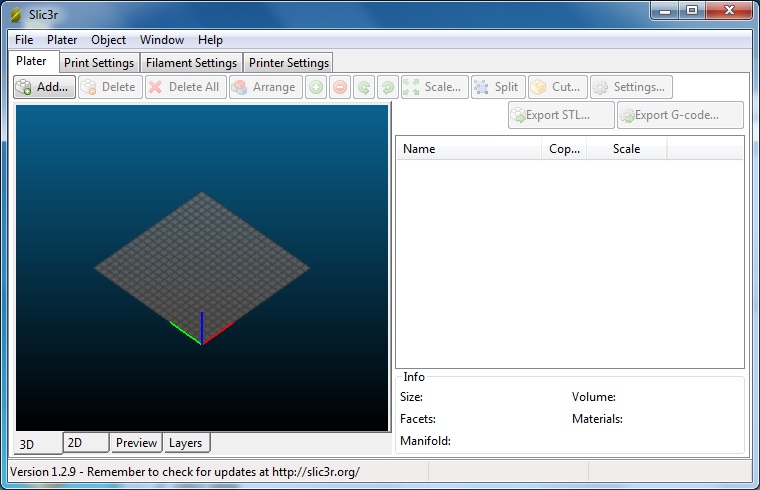
Select the file you wish to add. Below I've attached a sample you could use, you may also choose to find a different sample from online sources like GrabCAD.
The part will appear in the screen.
Inside the 3D view, right click the part to flip, rotate or scale it accordingly. 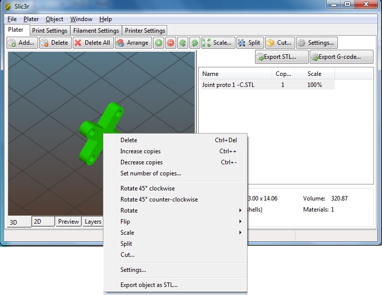
You can also choose to select Add... again if your part is small and you would like to print both at the same time. Do remember to place enough space between the two parts.
Select Export G-Code to generate the g-code. The G-code file will be opened by the Pronterface. 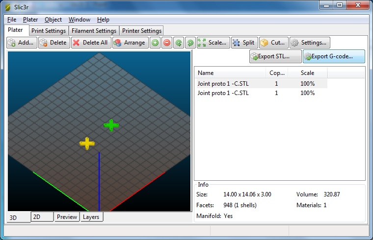
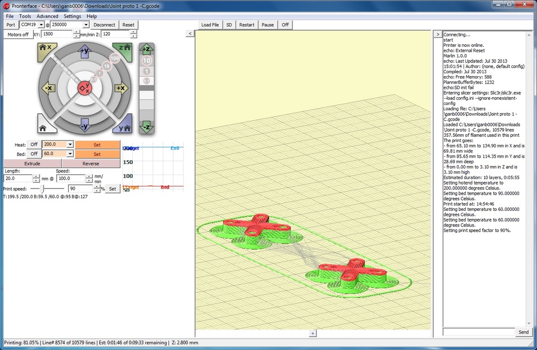
STEP 5From Pronterface, select Load File and select the g-code file generated using Slic3r.
Left-click and drag to rotate the part for viewing. 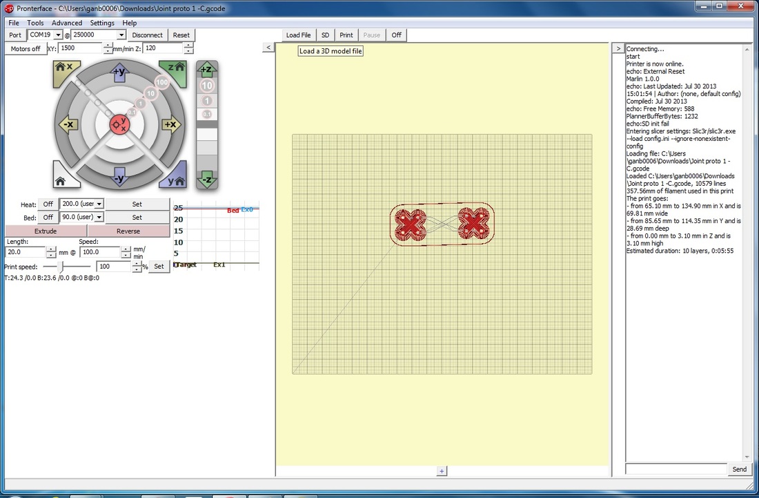
Select Set (highlighted in orange) for heating of the nozzle tip and heat bed.
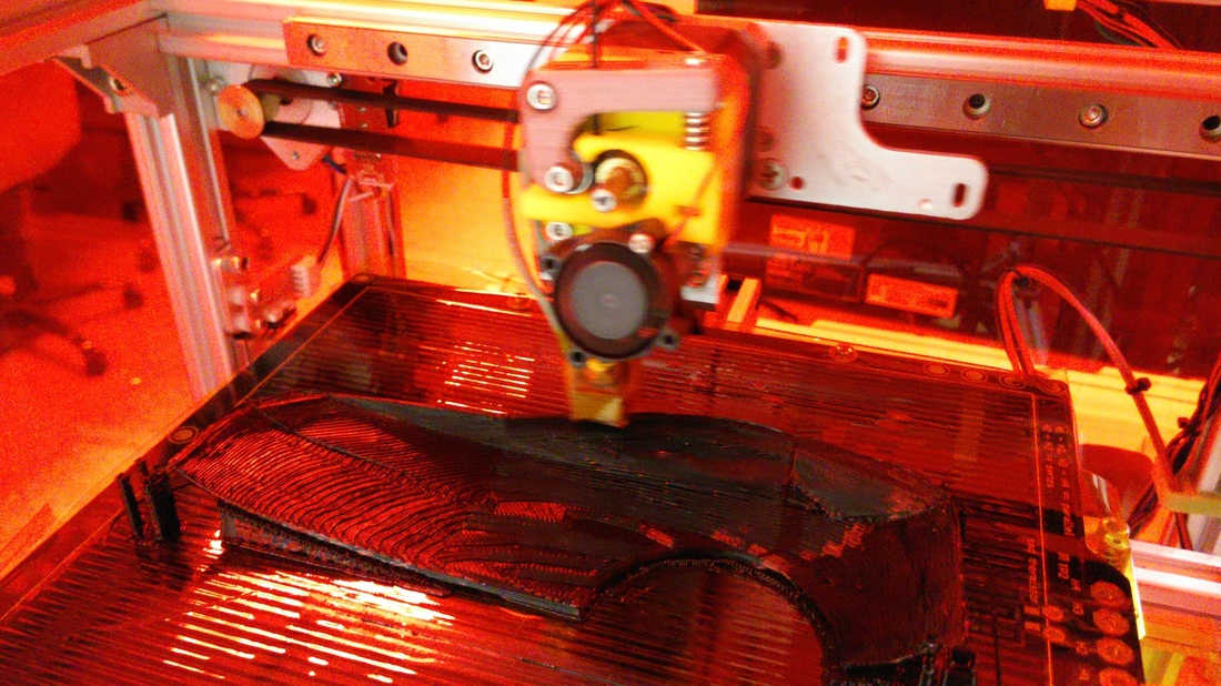
Select Print, when both nozzle tip and heat bed are heated enough, it will start printing. To see the printing progress and estimated timing, refer to the very bottom of the window. 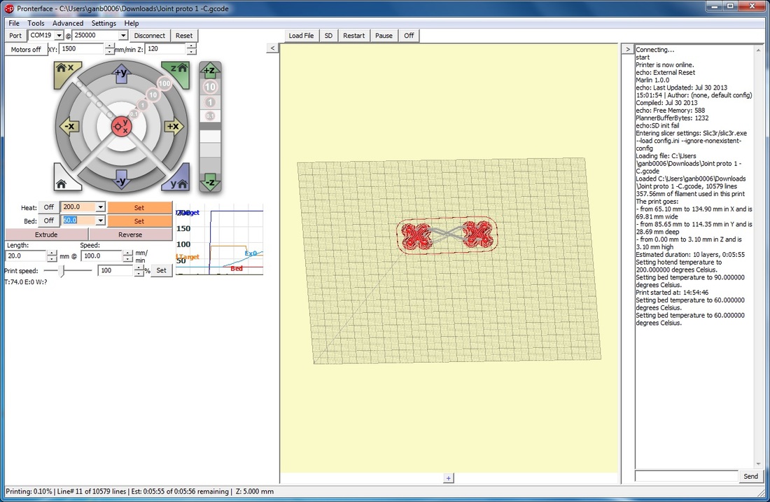
Parts that are green shows what has been printed, while red shows the remaining parts.
Once print has been completed, turn off the heat and left it cool down.
Wait a while before removing the part, as you may damage the part or burn yourself. COMPLETETIPS
Sometimes it takes a while to figure out your printer... 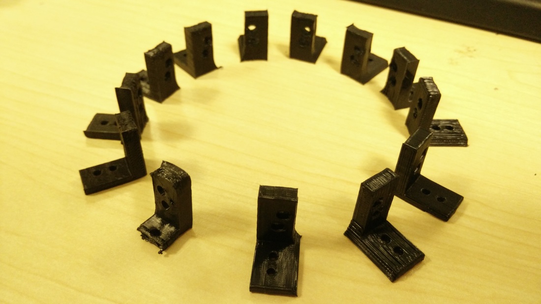
USEFUL LINKSThe links below were referenced in creating the summary above, do refer to them for further details.
| ||||||||||||