|
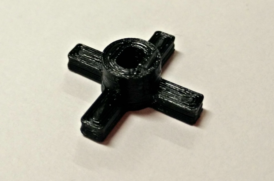
The following is a tutorial to teach you step by step how to create an Wheel Holder using the educational version of Autodesk Invertor Professional. If you have yet to install it, you may refer to the link below.
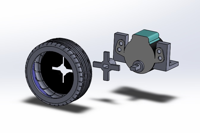
This base plate dimensions were drafted in consideration of the following components:
Here's a few good things to remember before we begin:
As this serves as a tutorial, there are intentional hiccups along the way to give you a better learning experience of what to look out for in the future.
LET'S START!STEP 1Launch Autodesk Inventor Professional.
The homepage will appear as shown below. Select PART to create a new part. WHAT IT MEANS: 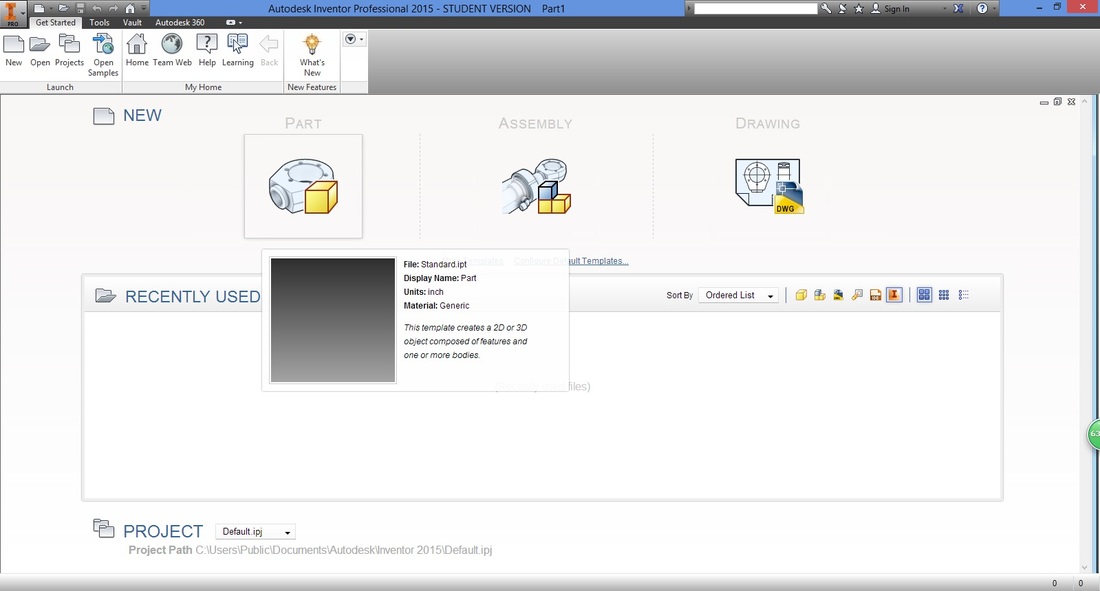
STEP 2 (IMPORTANT)A good habit to have is to check and set the dimensions of your drawings.
Under the Tools ribbon, select Document Settings. 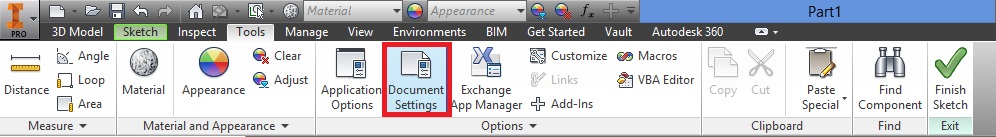
A window will then appear.
Select the Units tab, and adjust accordingly. 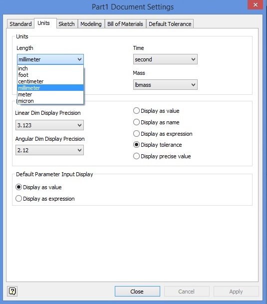
Select Apply then Close, to apply settings.
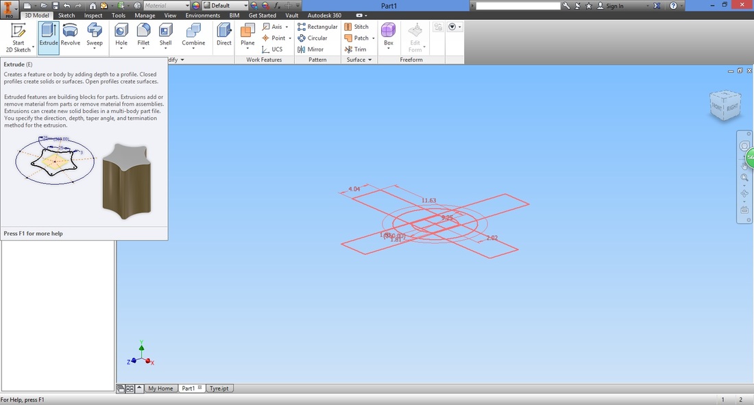
STEP 3In the 3D Model ribbon, select "Start 2D Sketch".
Notice that if you hover over the function for long, a quick introduction of the function will appear. 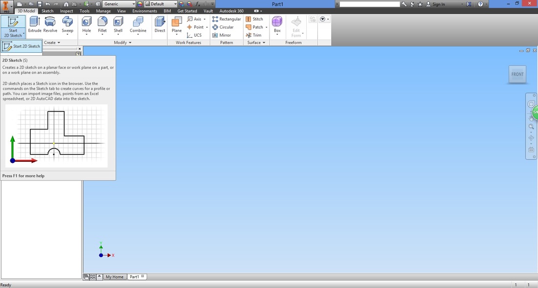
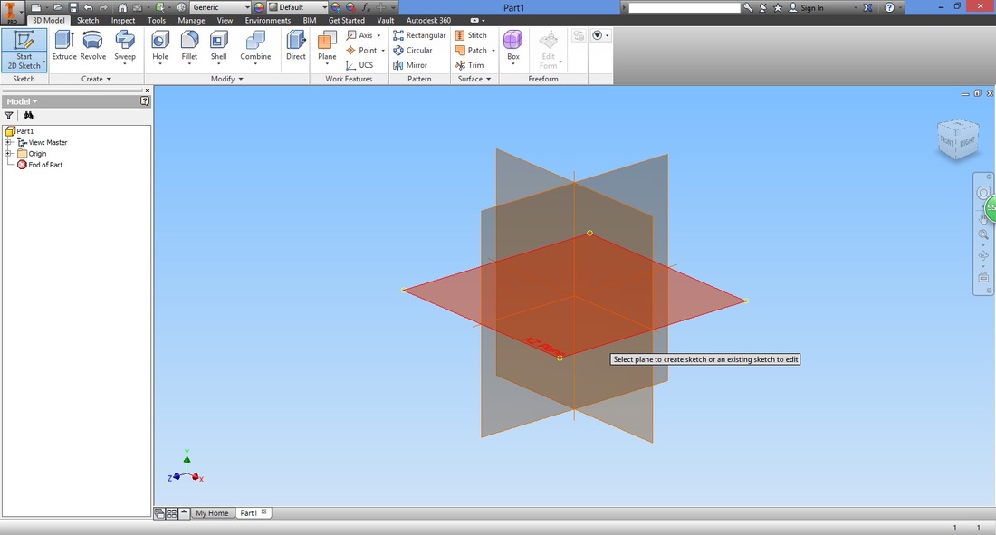
Next, select the plane you would want to draw on. Here I've selected the XZ Plane.
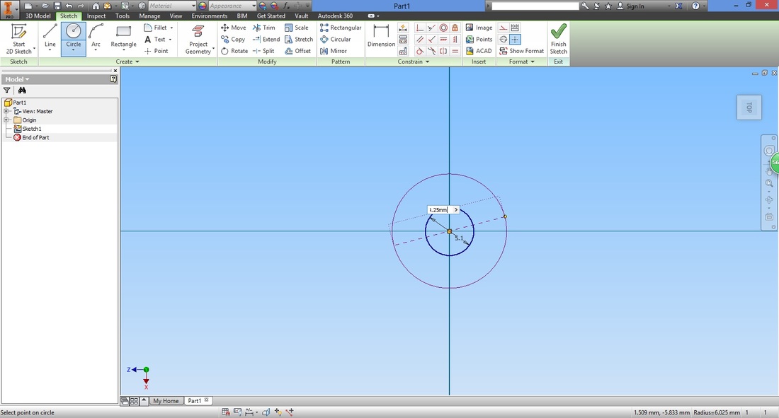
WHAT beginners SHOULD KNOW: STEP 4
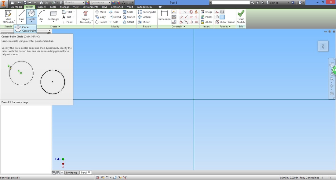
Type in the diameter of the circle.
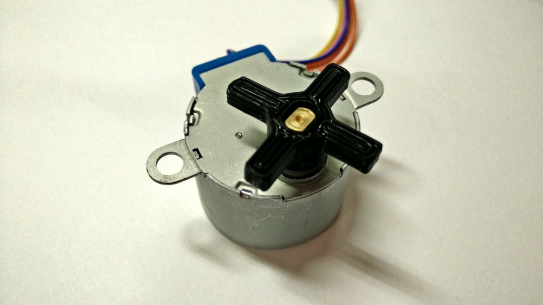
THE DIMENSIONS OF THE circle HERE IS TO ACCOMMODATE THE BYJ48 STEPPER MOTOR. MODIFY IT BASED ON YOUR REQUIREMENT. 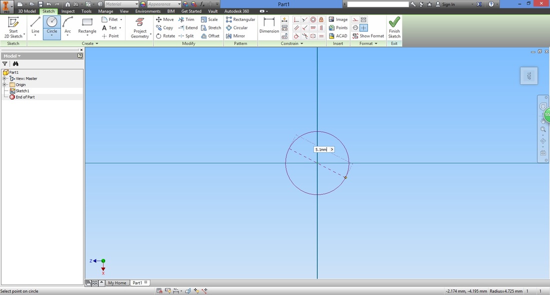
Draw another circle bigger than the one before.
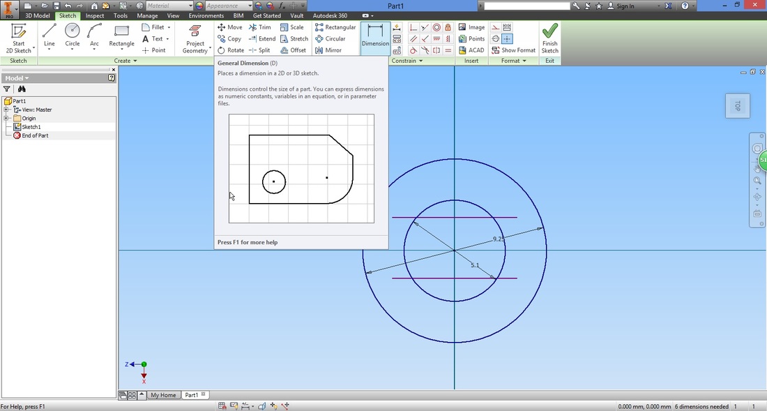
STEP 5
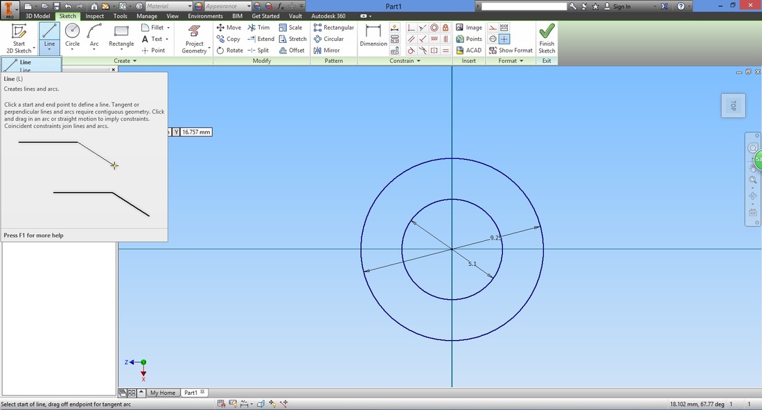
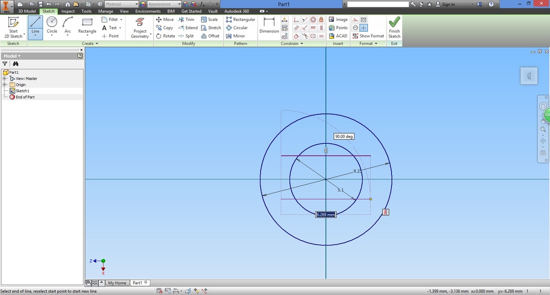
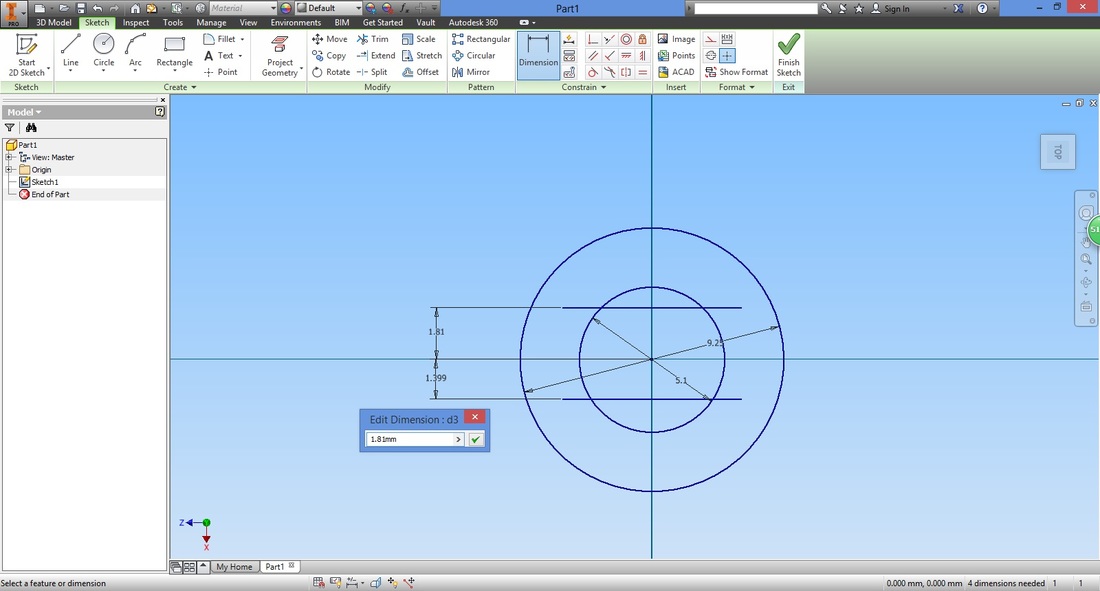
Select the Dimension function.
Distance the top line from the origin by selecting them, then inputting the distance.
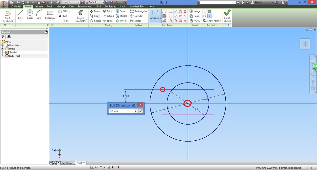
Repeat for the bottom line.
STEP 6
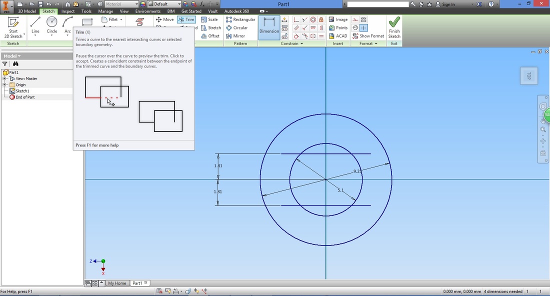
If you are unsure what to trim, you may also refer to the slide show below (in sequence).
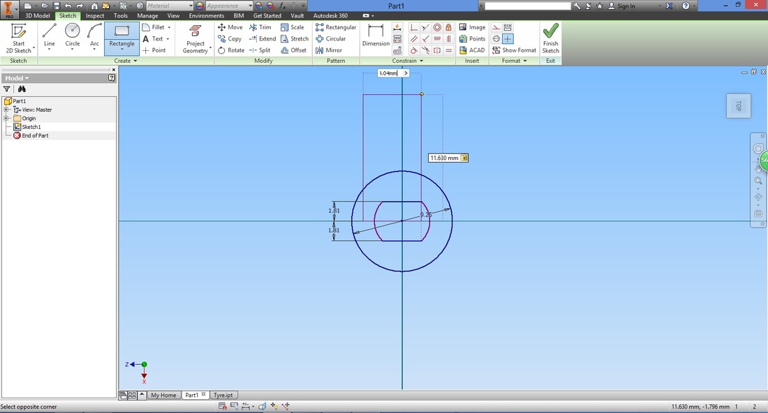
Step 7Next, we draw the '+' sign of the part. Select the Rectangle function.
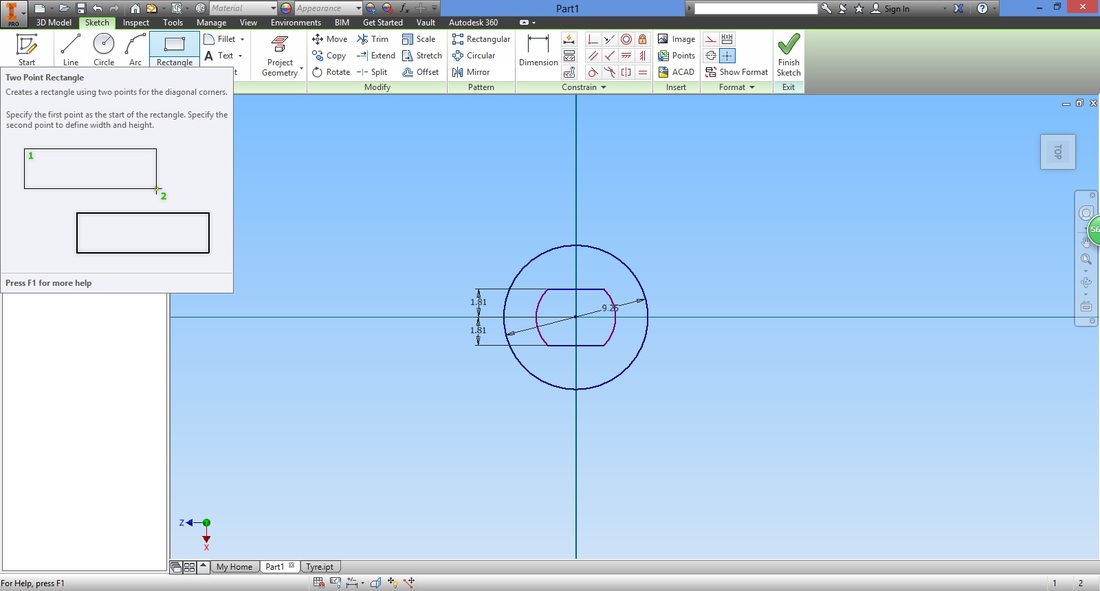
Draw the rectangle. Input the length, and without exiting (pressing Enter), select the next input field and type in the width.
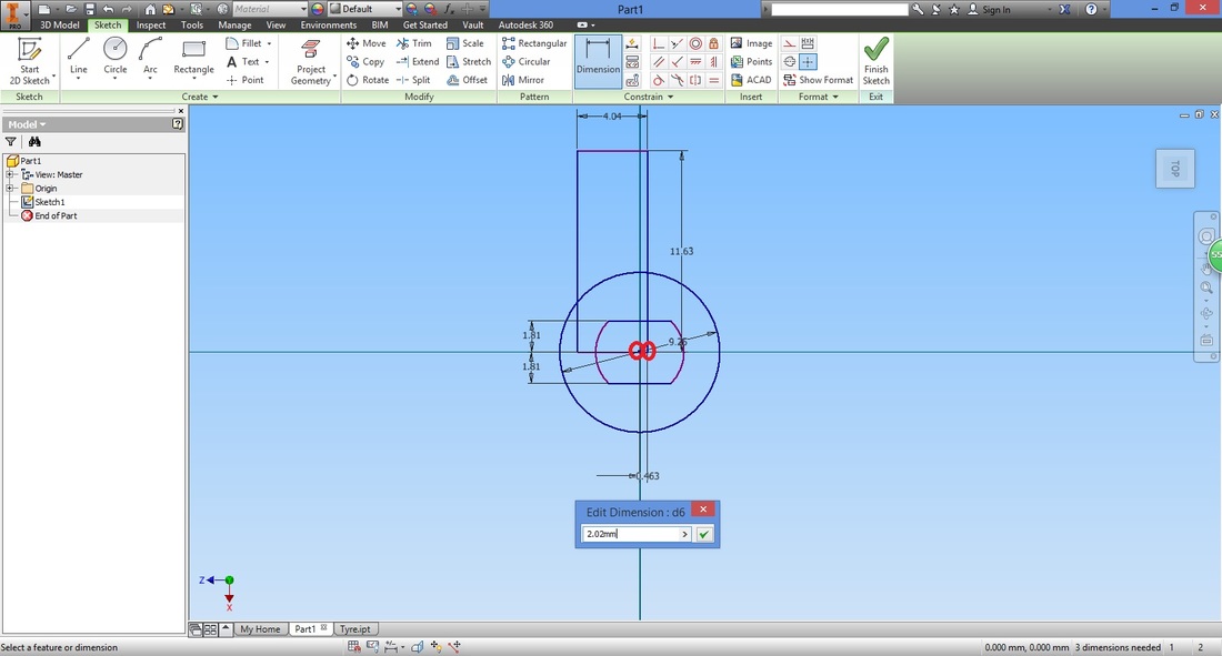
Select the Dimension function. This time position the rectangle so that the midpoint of the bottom horizontal line is coincident to the origin.
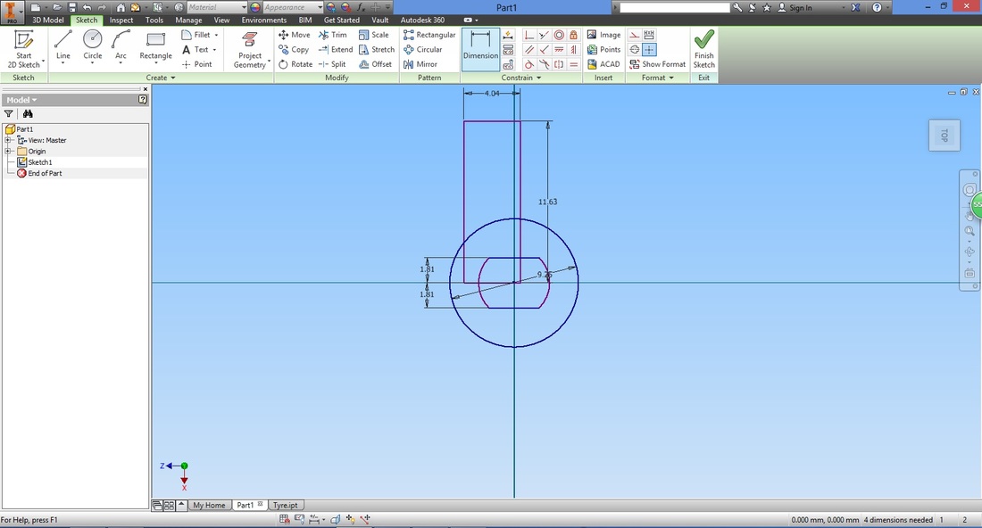
Select the bottom right edge of the rectangle and the origin. Input its distance.
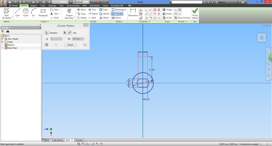
step 8Now we want to orientate the rectangle around the origin. To do so, select the Circular Pattern function.
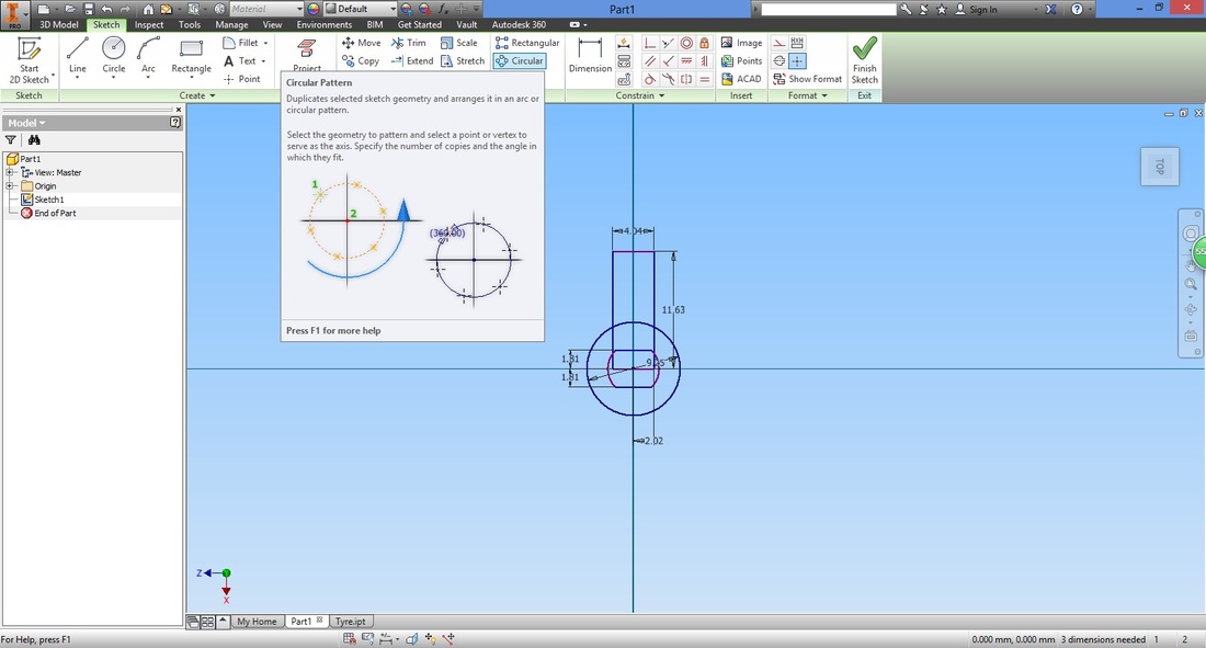
Select the rectangle.
You can do so by
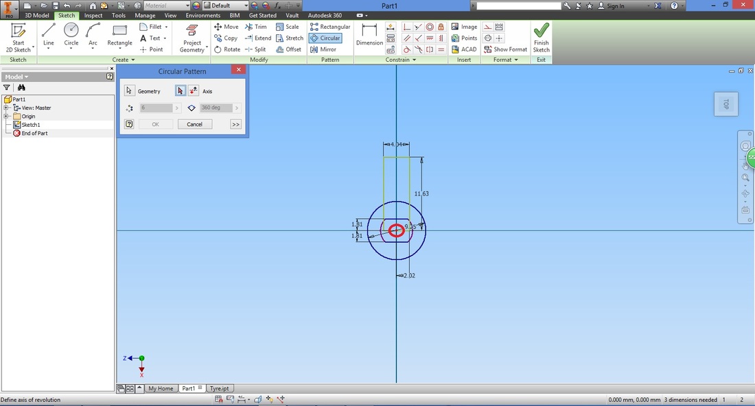
Select Axis in the Circular Pattern window, then select origin.
Configure the settings.
Note that the no. of patterns field includes the original. 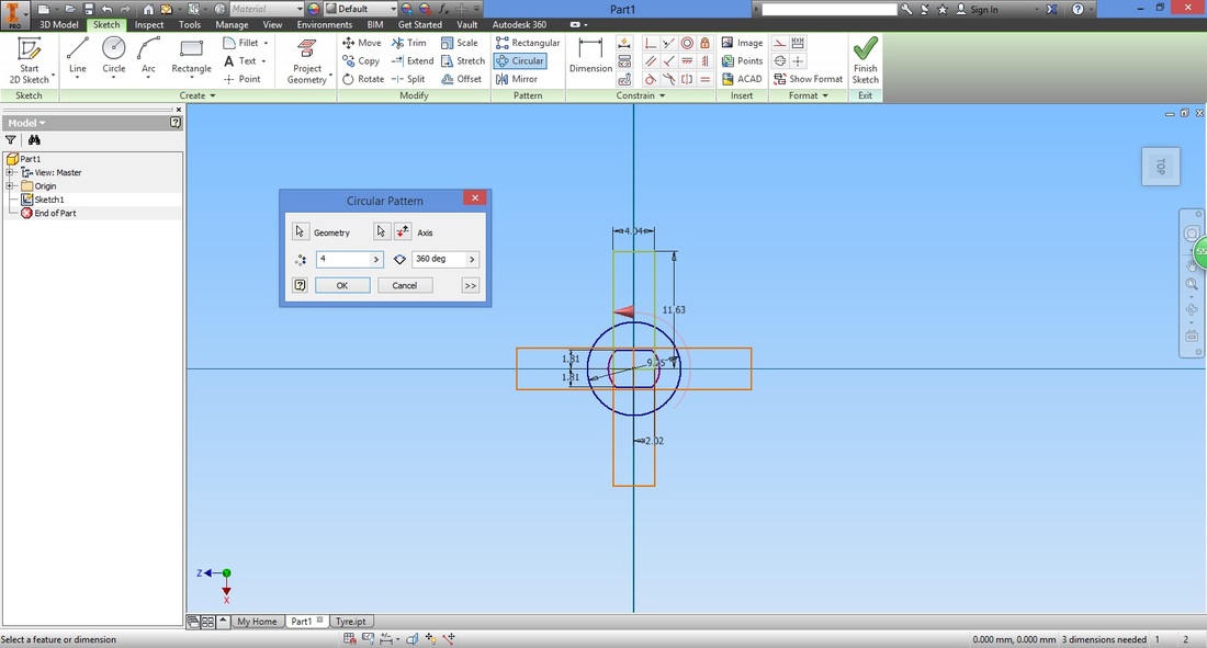
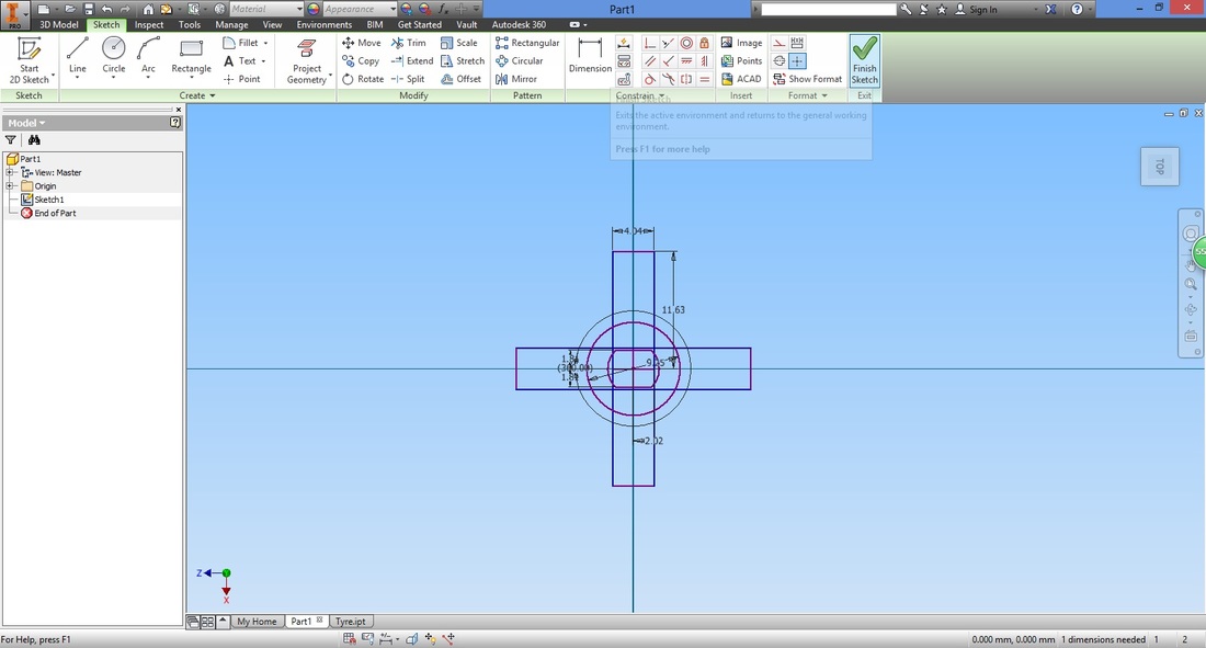
CAN we have more than 4 patterns? Once completed, exit the sketch.
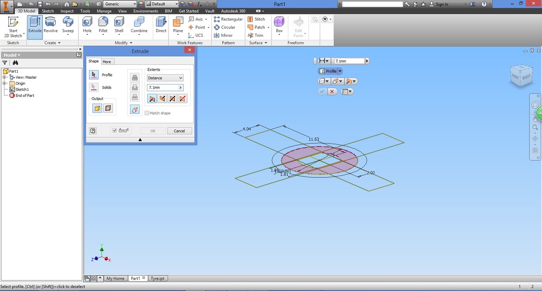
step 9Select the Extrude function.
Select the profile to extrude and configure the settings.
Step 10This step will show you how to share a sketch so that it can be used for other functions.
Right-click the sketch in the Model panel and select Share Sketch. 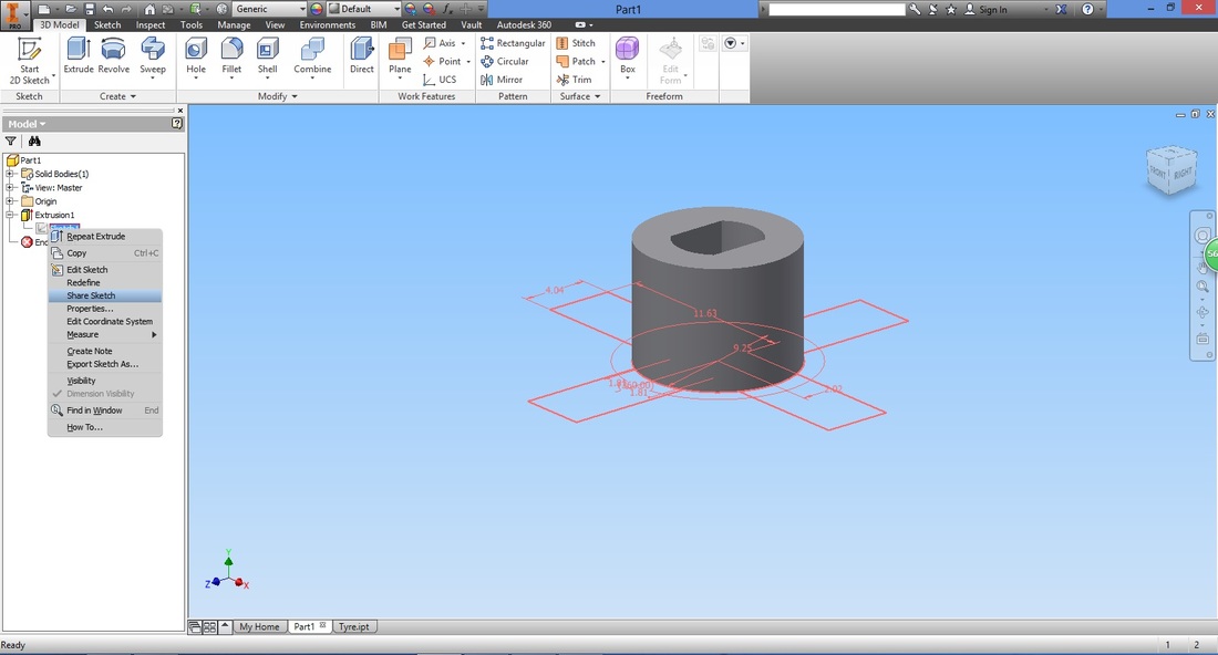
Go to the extrude function again, this time highlight the '+' section.
Configure the settings similarly. The distance however should be less of the previous cylindrical extrusion. 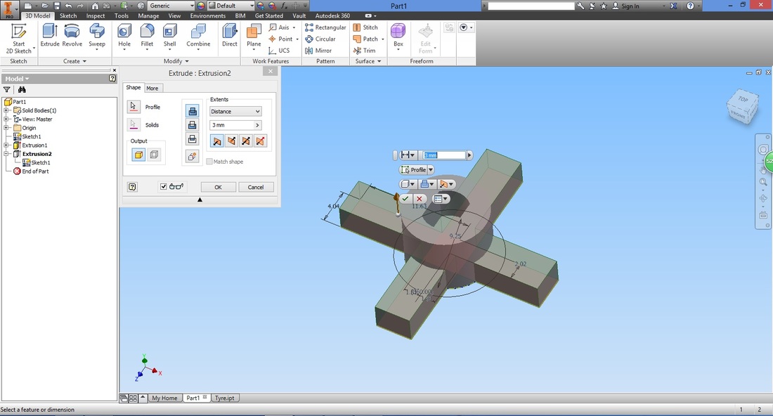
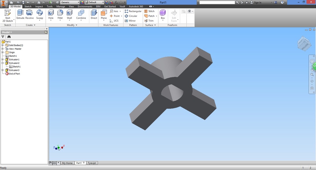
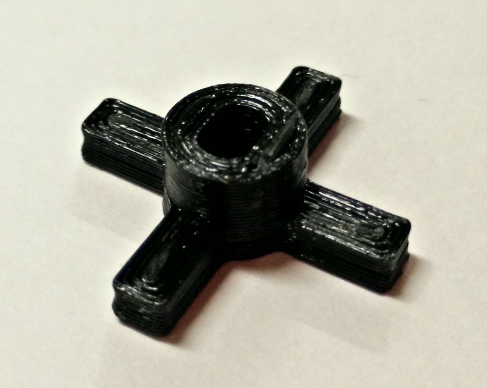
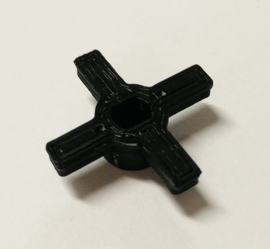
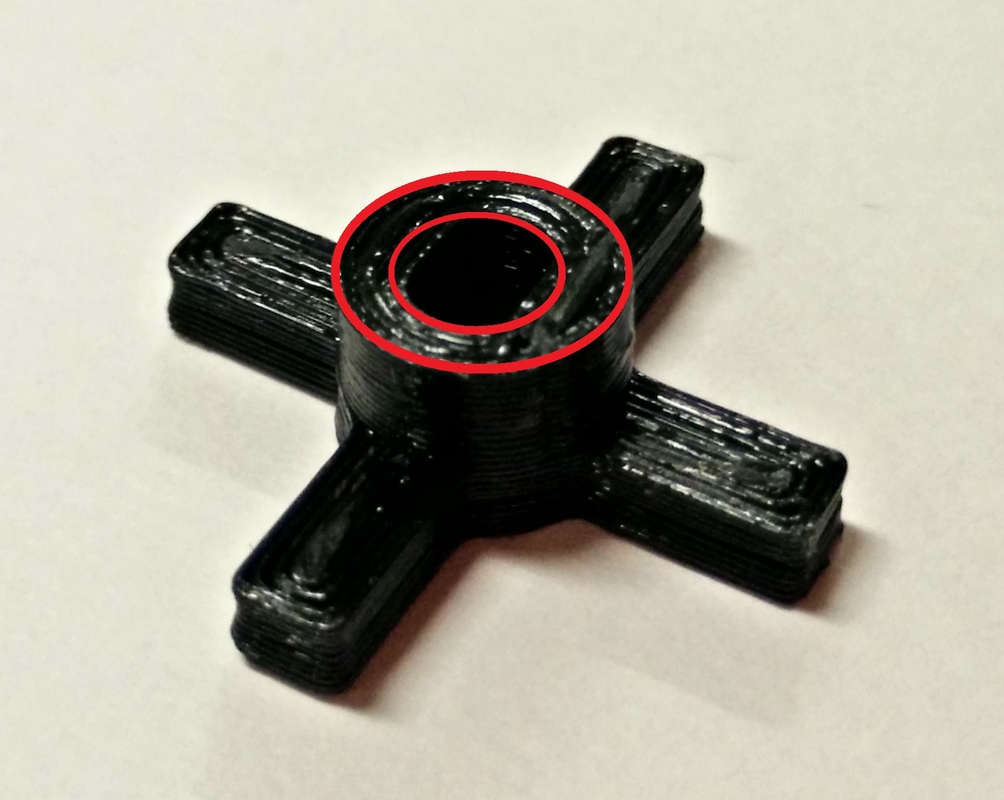
Step 11Notice how the centre of the part is no longer hollow.
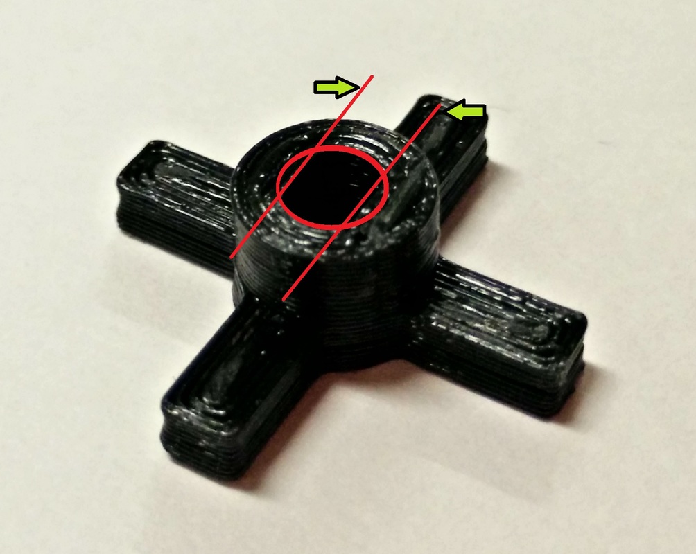
Select the Extrude function. This time we will use its cut type operation. 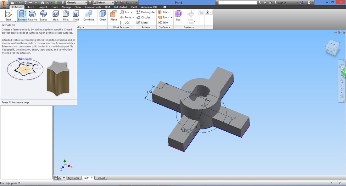
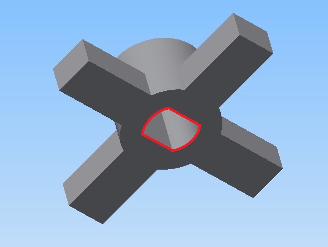
Select the profile, then the cut type operation, and change the Extents to All.
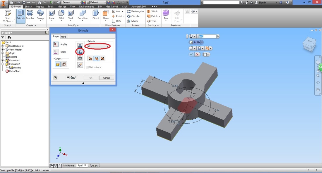
You will have something like this.
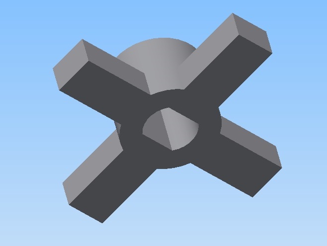
CONGRATULATIONS!
| ||||||||||
Download Wheel holder file |
| ||
