|
The following is a tutorial to teach you step by step how to create an I-shaped base plate using the educational version of Autodesk Invertor Professional. If you have yet to install it, you may refer to the link below.
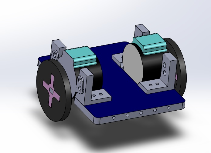
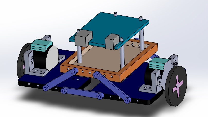
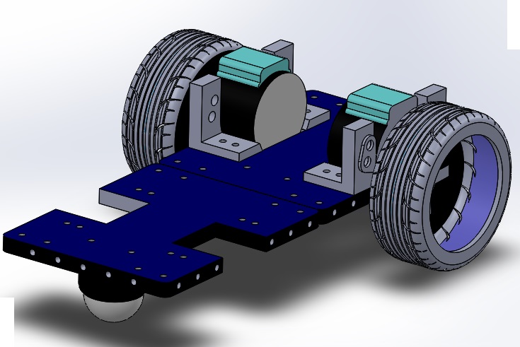
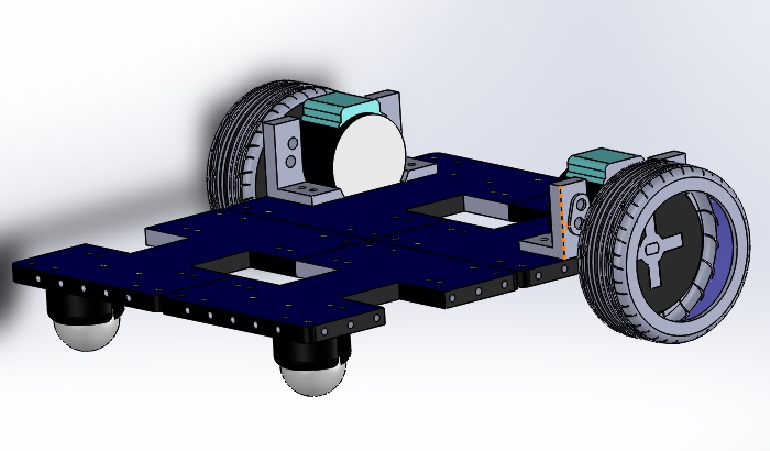
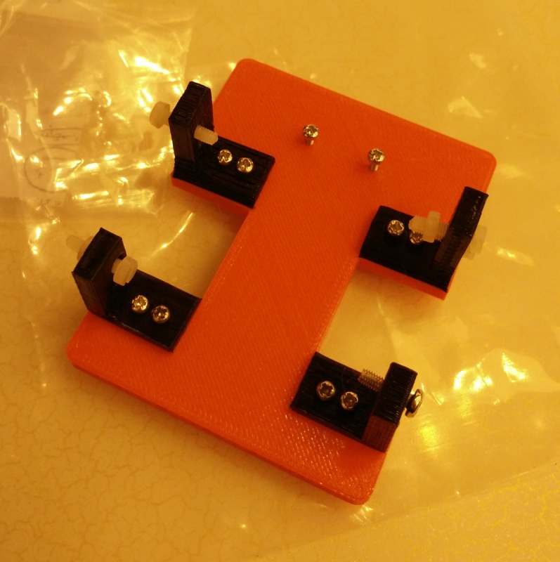
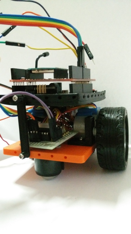
This base plate dimensions were drafted in consideration of the following components:
Here's a few good things to remember before we begin:
As this serves as a tutorial, there are intentional hiccups along the way to give you a better learning experience of what to look out for in the future.
This tutorial is broken into two phases.
The first phase is targeted for beginners where you will learn to sketch, mirror, fillet, extrude etc. The second phase will give you the experience of going back to the sketch to incorporate new changes and mainly for completeness, as it will allow you to incorporate the other components mentioned above. LET'S START!First phaseSTEP 1Launch Autodesk Inventor Professional.
The homepage will appear as shown below. Select PART to create a new part. WHAT IT MEANS: 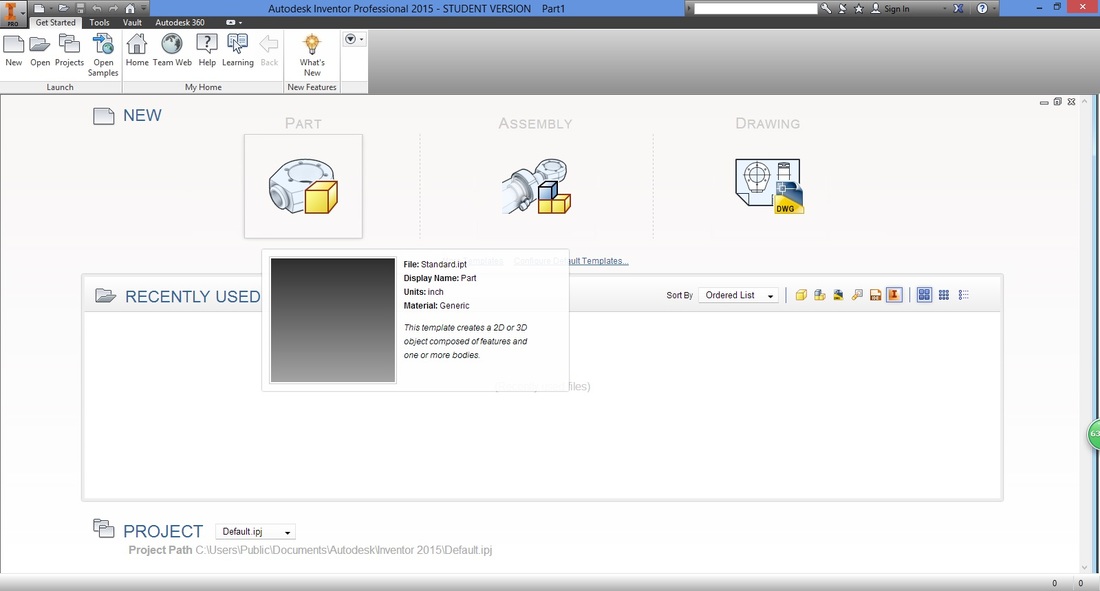
STEP 2 (IMPORTANT)A good habit to have is to check and set the dimensions of your drawings.
Under the Tools ribbon, select Document Settings. 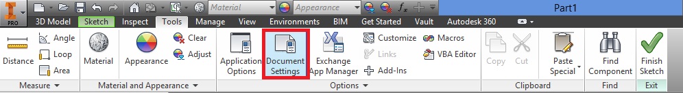
A window will then appear.
Select the Units tab, and adjust accordingly. 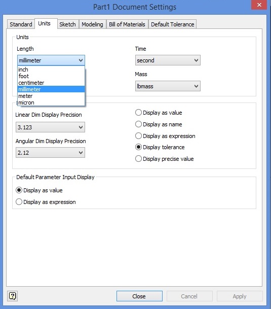
Select Apply then Close, to apply settings.
STEP 3In the 3D Model ribbon, select "Start 2D Sketch".
Notice that if you hover over the function for long, a quick introduction of the function will appear. 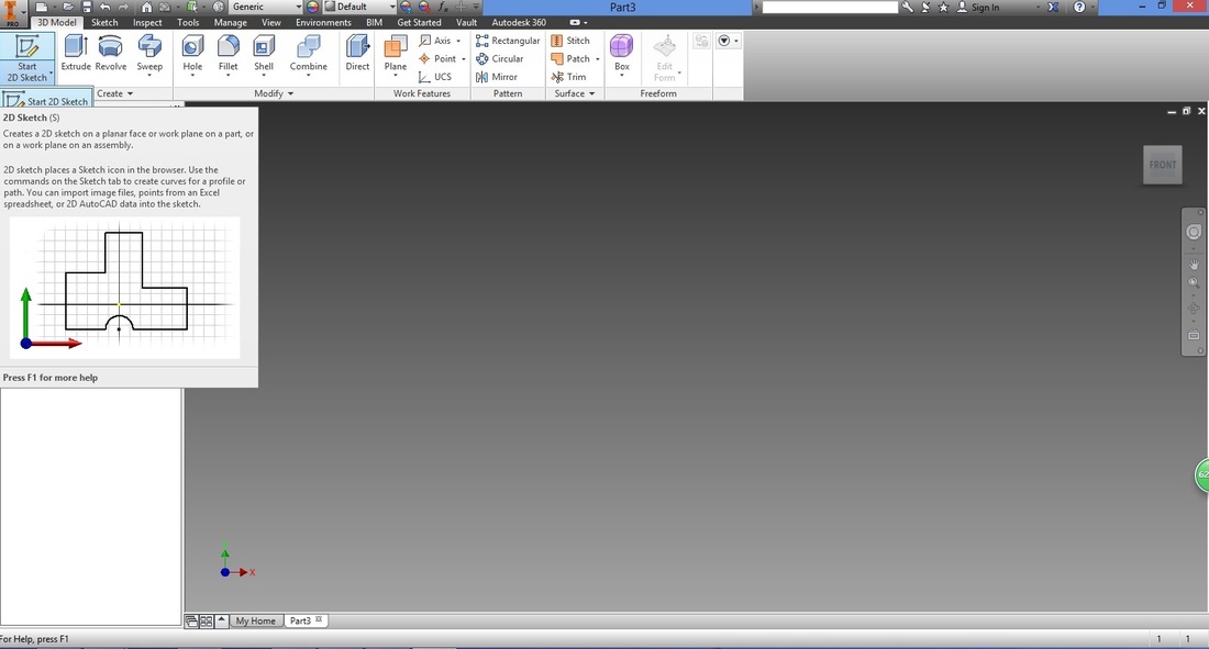
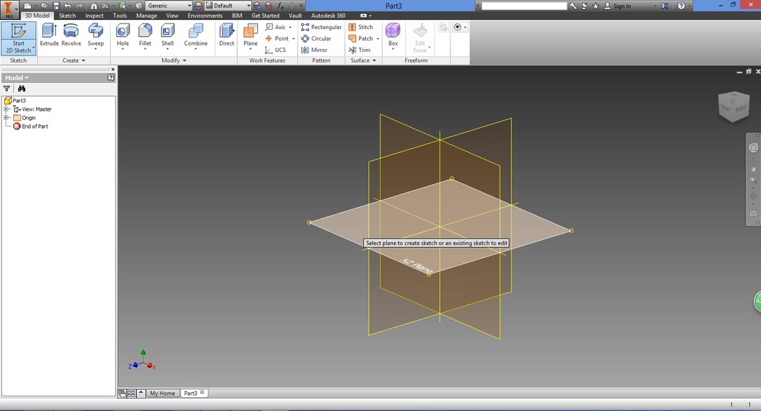
Next, select the plane you would want to draw on. Here I've selected the XZ Plane.
WHAT beginners SHOULD KNOW: STEP 4From the Sketch ribbon, select the Rectangle function.
There is more than one way to draw a rectangle. Here We use a two point type, where two points diagonal of each other have to be determined (e.g. bottom left and top right) 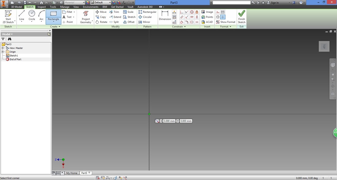
Hover over the origin, and when the circle turns green, left click it. This gives you the first point of the rectangle.
Next, move right and upwards and you will see the dimension of the rectangle. Notice that one of the dimensions are highlighted in blue. 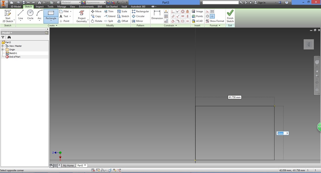
Without clicking anything, type the length desired. You should now be able to see your mouse pointer again. Select the width dimension.
The dimensions of the rectangle is based on the size of the arduino uno with additional allowance. If you have a desired size for your base plate, you may choose to modify it accordingly. 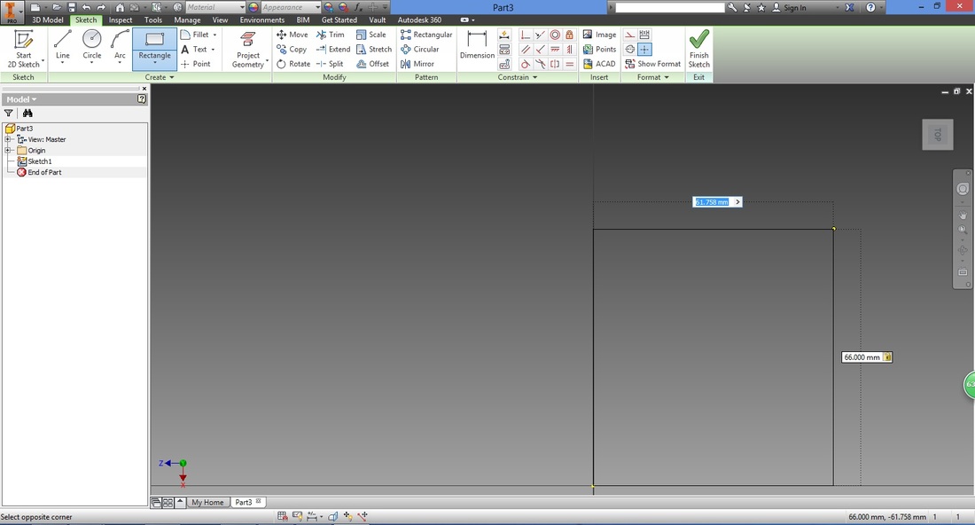
Once completed, press "Enter".
Note that you are still in the Rectangle function where you can continue to draw another rectangle. To exit the function, press "Esc". If the function is still highlighted in blue, you are still within the function and require to press "ESC". 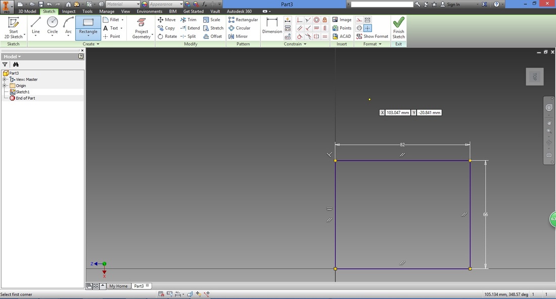
STEP 5Let's call the rectangle completed Large Rect and the next one Small Rect.
Draw another rectangle- Small Rect. (Select the Rectangle function if you have exited) Move the cursor along the left line of Large Rect, you should see a yellow circle. Left click anywhere along the line. Learning to trace along drawn lines are useful as they ensure that the new line being drawn is connected to the one being traced. 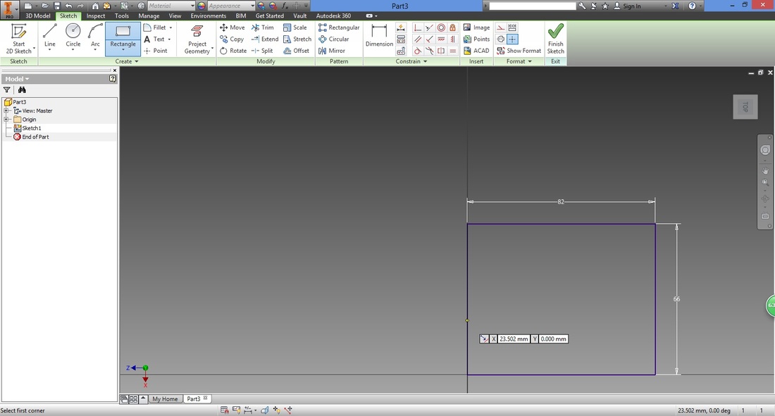
Similar to the first rectangle, type in the desired dimensions.
THE DIMENSIONS OF THE second RECTANGLE here IS to accommodate the BYJ48 Stepper Motor. Modify it based on your requirement. 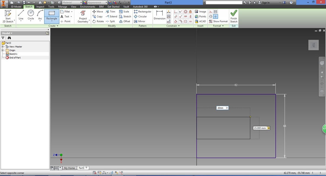
You should then have two rectangles as shown below.
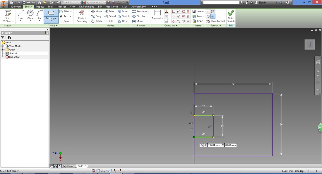
STEP 6Next we want to repeat a rectangle from the right line of Large Rect.
There are two obvious ways to do so: draw a rectangle or mirror the existing one. Here we will use the Mirror function.
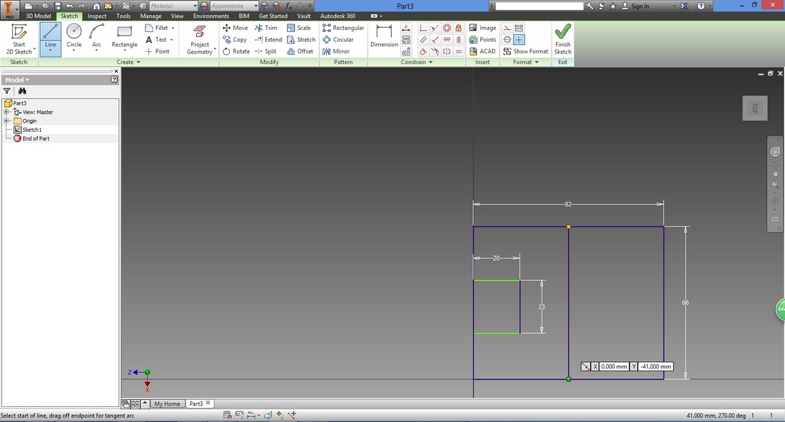
First, we will create the line to mirror about. Select the Line function. Trace the top line of Large Rect until a green circle is shown. This is the midpoint of the line, left-click it. 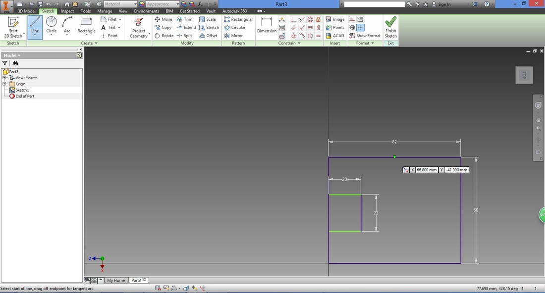
Trace downwards to the midpoint of the lower horizontal line, and left-click.
Note that the angle at which the line is being drawn will be shown. (Here it shows 180 deg for the vertical line downwards) 
You will then have the following.
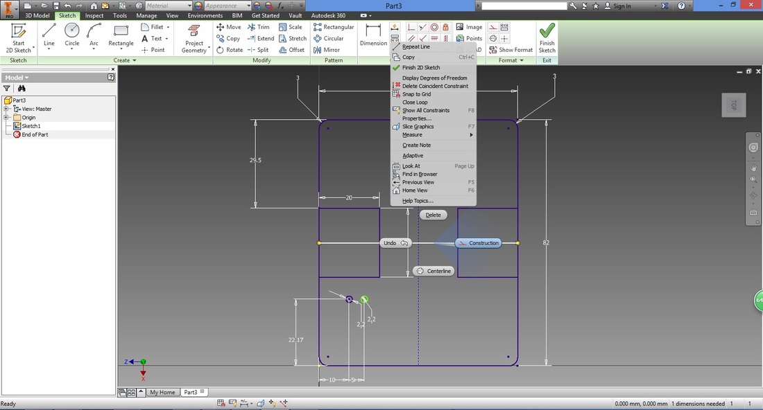
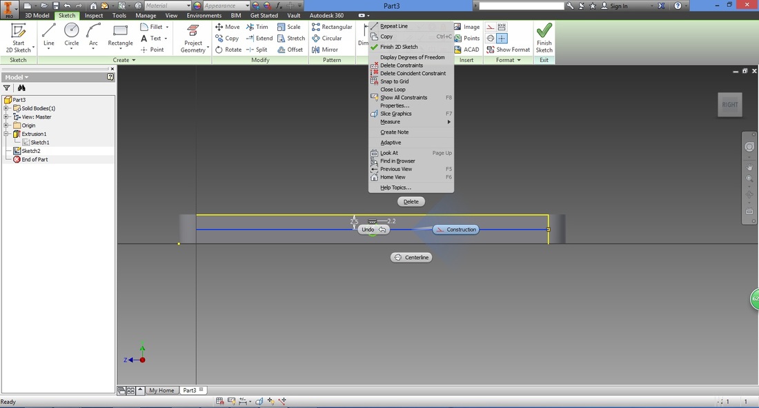
As this mirror line is used for construction of the part, it is good practice to change this into a Construction type line.
To do so, right click the line created. A menu as shown below will appear. Select Construction. (You can also change a construction line back by deselecting this function in the same way) 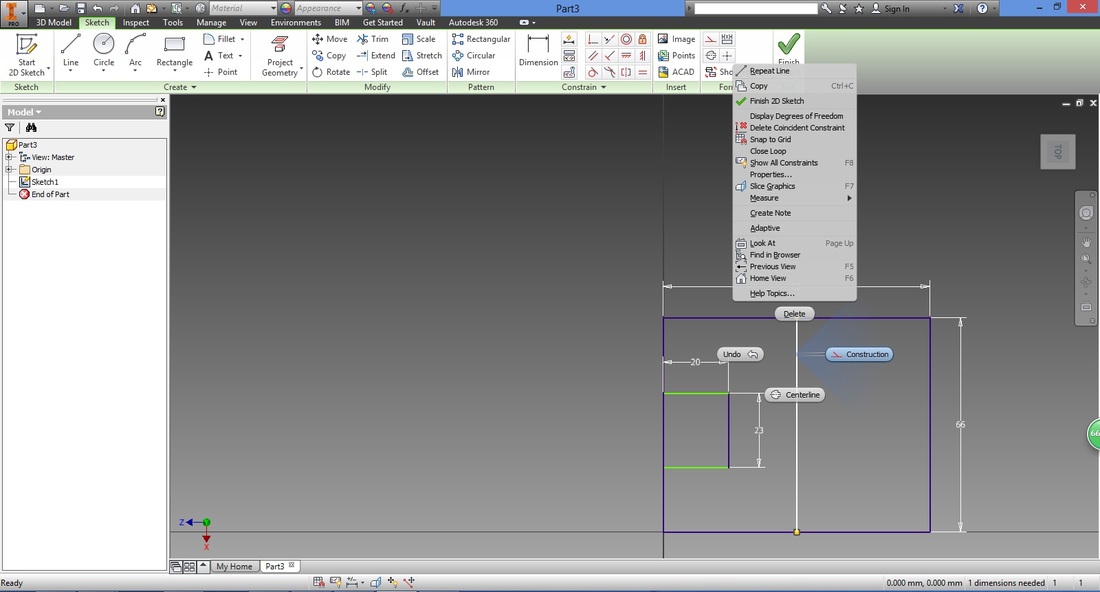
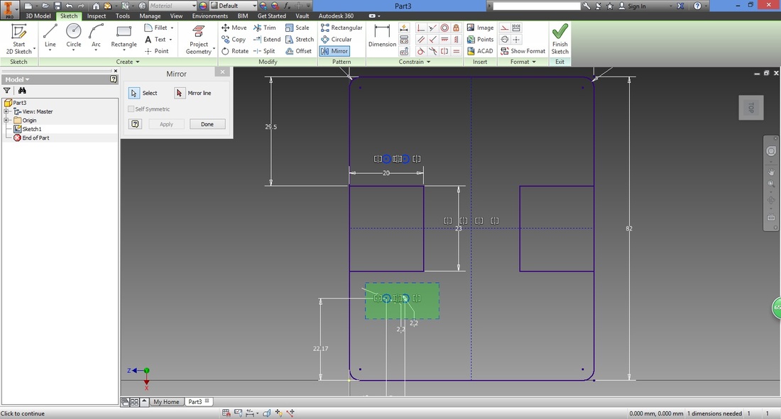
Select the Mirror function from the Sketch ribbon under Pattern.
Select the lines we wish to mirror. There are two ways to select multiple lines: 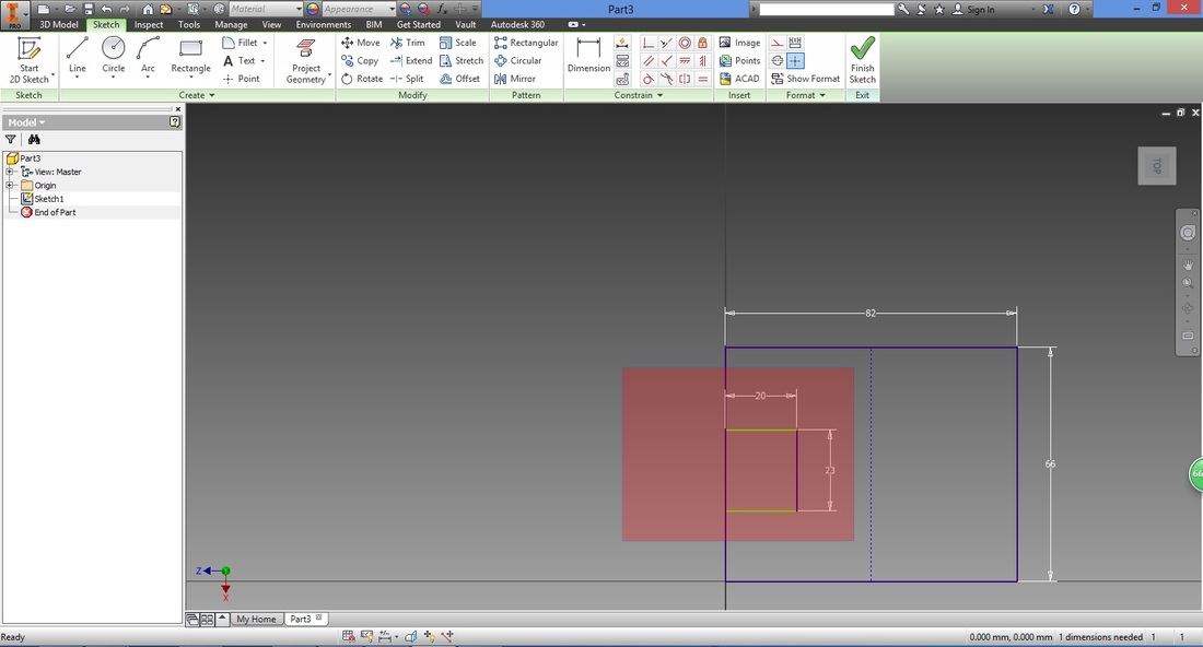
Selected lines will turn blue.
Next, in the Mirror window select Mirror line. Left-click the construction line created earlier. The parts selected will be mirrored over the mirror line. 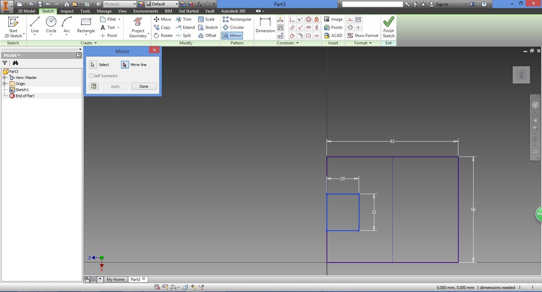
A preview will be shown and the Apply button is selectable in the Mirror window.
Select Apply. If all desired parts have been mirror, select Done in Mirror window. Note that if Apply is not selected, the mirror function will not be executed. 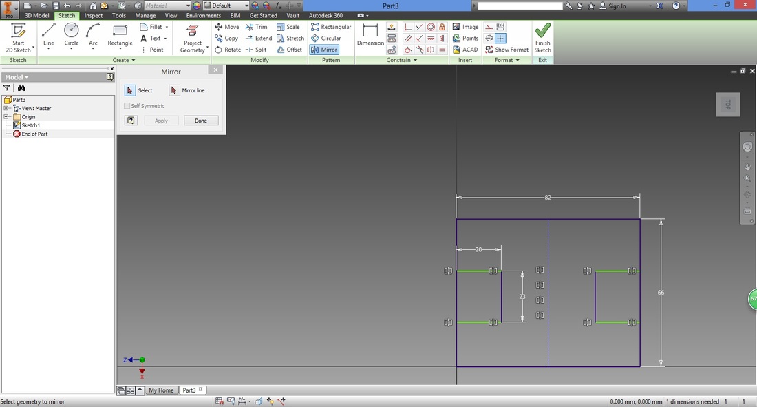
Step 7Next, use Fillet function to make the sharp edges round.
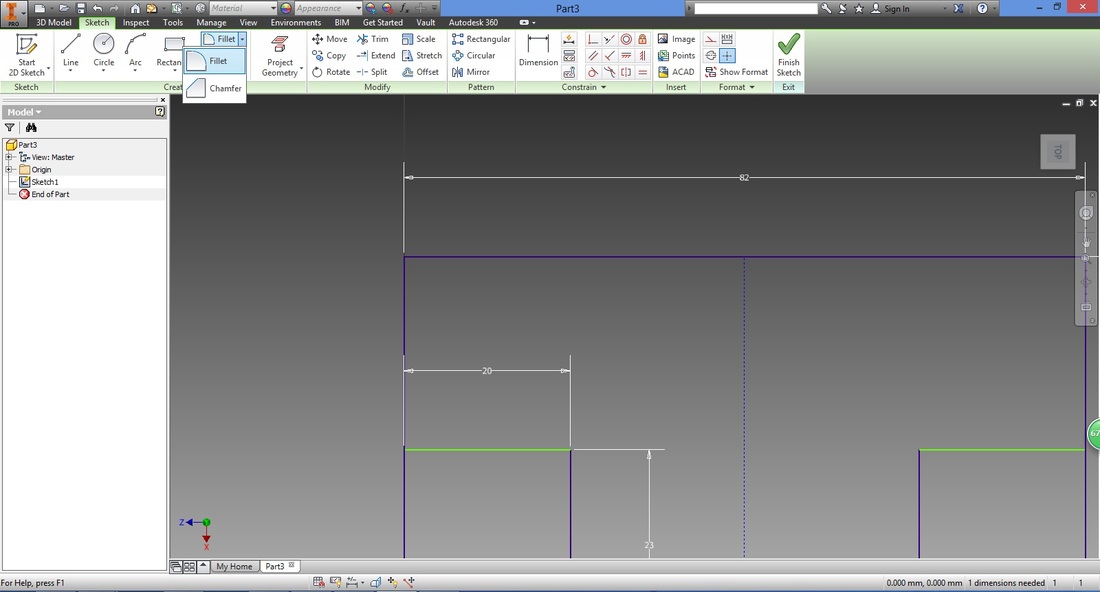
To zoom in, use the scroll on your mouse. 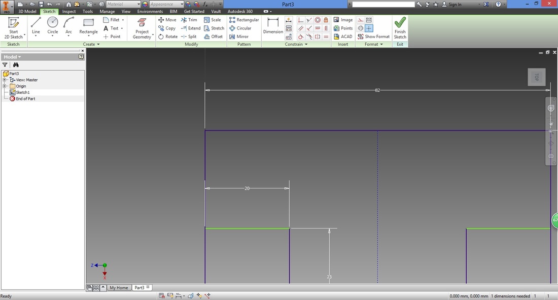
Type in the radius desired.
Left-click the left vertical line of Large Rect. 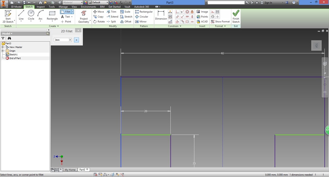
Left-click the horizontal line connected to it.
Note that the fillet function requires both lines to be connected (e.g. not parallel to each other) 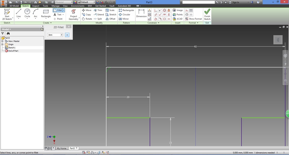
A larger radius will result in a larger curvature.
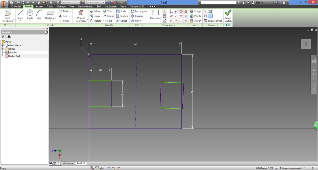
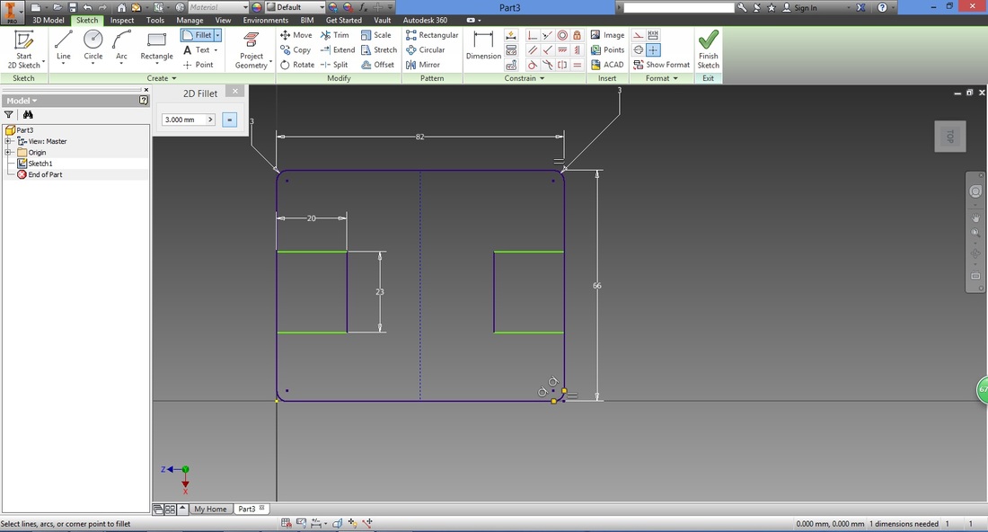
Select the next corner and repeat for remaining corners.

Once four corners are completed, it will be as shown below.
Learning point: step 8 (Correcting dimension step)This step illustrates how you can change the dimensions.
Select Dimensions function and the two lines you wish to dimension. 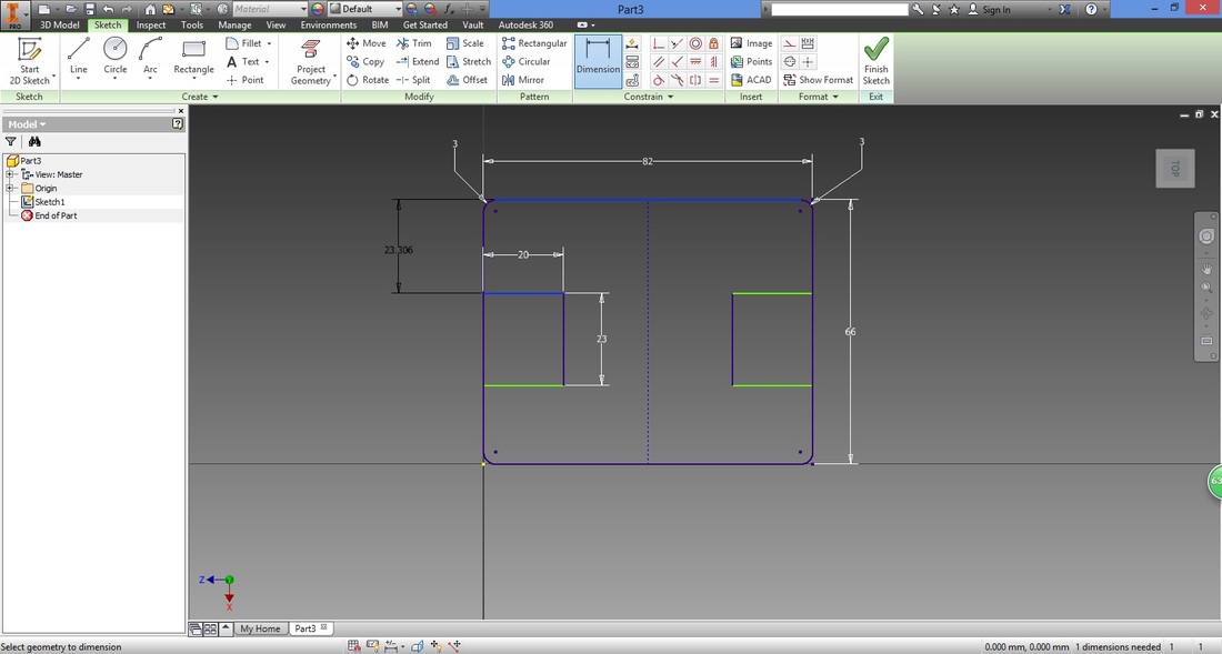
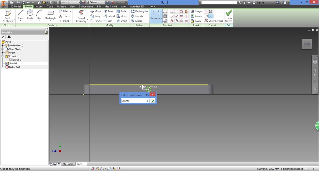
Left click the numerical value to change it.
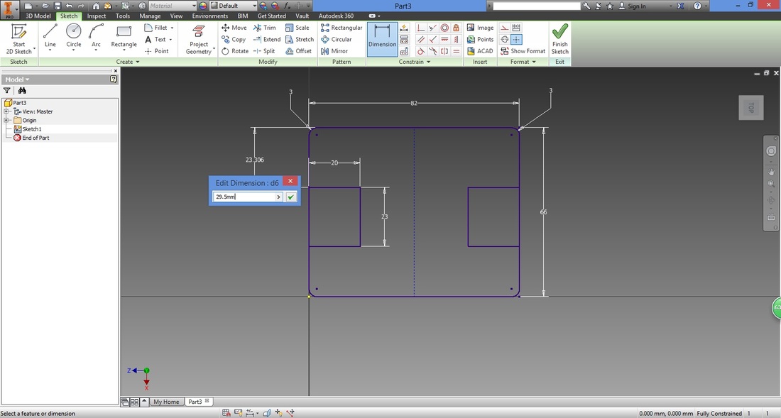
Here I've switched the length and width dimensions.
Do note that as we used a mirror line created from midpoint to midpoint, adjusting the dimension will adjust it accordingly. 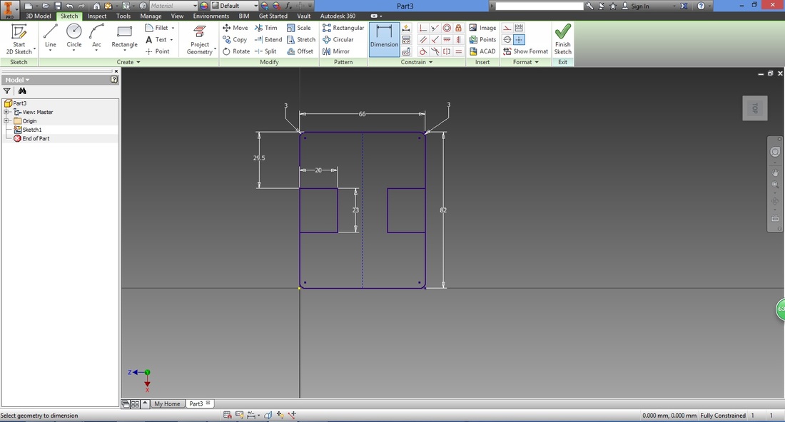
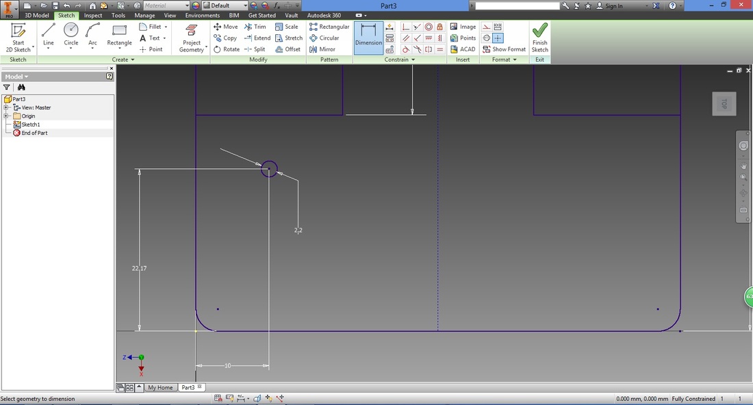
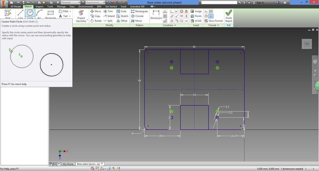
step 9Select the Circle function.
Left-click any point around the bottom left, then type in the radius. THE DIMENSIONS OF THE holes HERE are based on the screw size desired to mount the L-Bracket which holds the BYJ48 STEPPER MOTOR, together with the base plate. 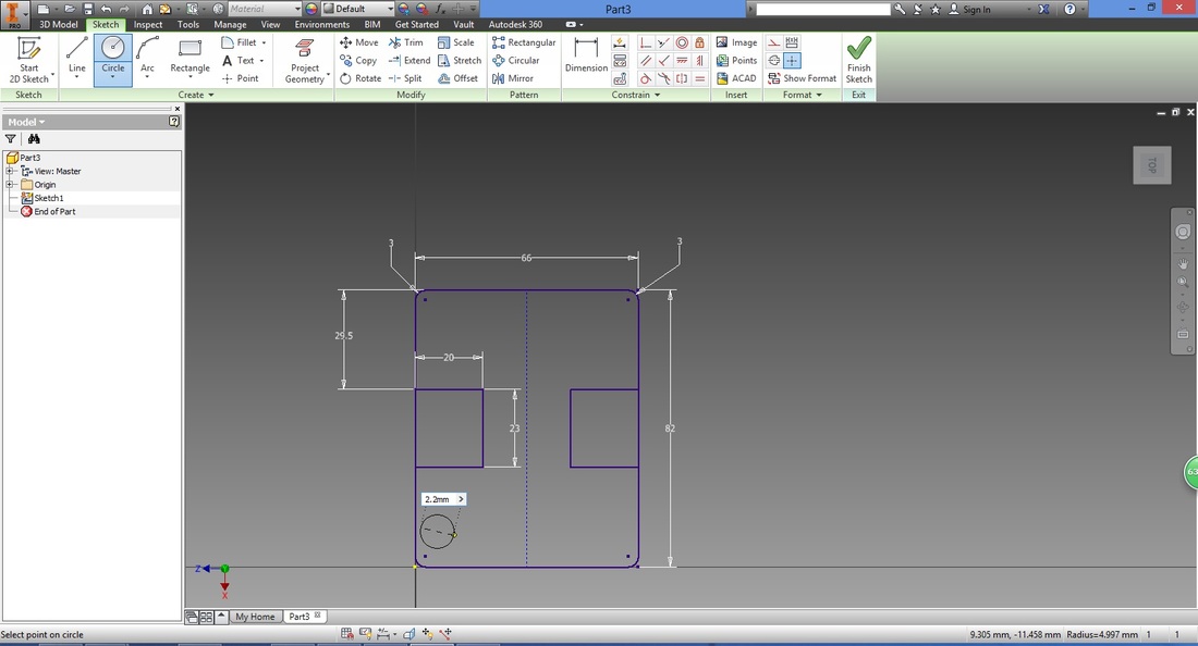
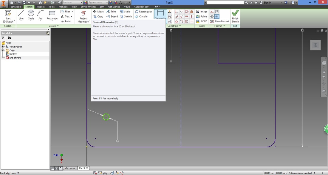
Use the Dimension function to position the circle accordingly.
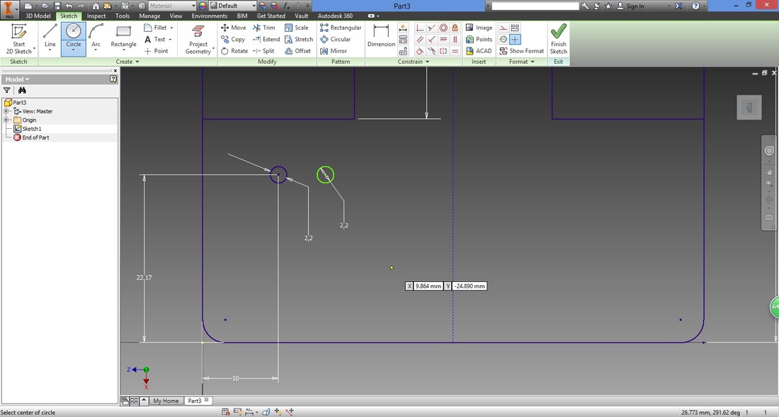
Select the Circle function again.
This time, trace the center of the circle you positioned. There will be a horizonal dotted line from the center of the circle you traced to your cursor. Left click and type in the radius. 
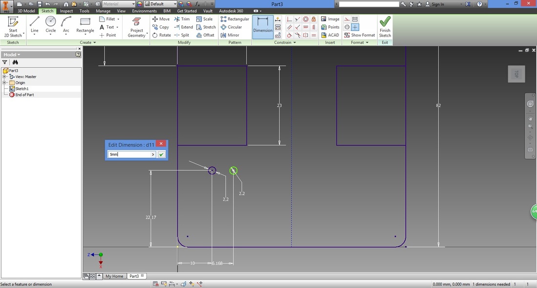
Use the Dimension function again and fixed the distance between the circles.
step 10Here we mirror the two circles to four corners of the base plate.
First, draw a line using Line function from the midpoint of the left vertical line to the midpoint of the right vertical line of the Large Rect. 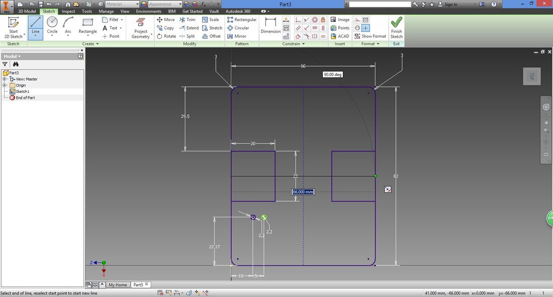
Next, we change this into a Construction type line, by right clicking the line and selecting Construction.
Select the Mirror function, and the two circles.

Select Mirror line in the Mirror window, and select the horizontal mirror line.
After clicking Apply, the mirrored circles will be shown. 
Without pressing Done, continue by selecting the four existing circles.
Select Mirror line from the Mirror window.
Select the vertical mirror line and press Apply. 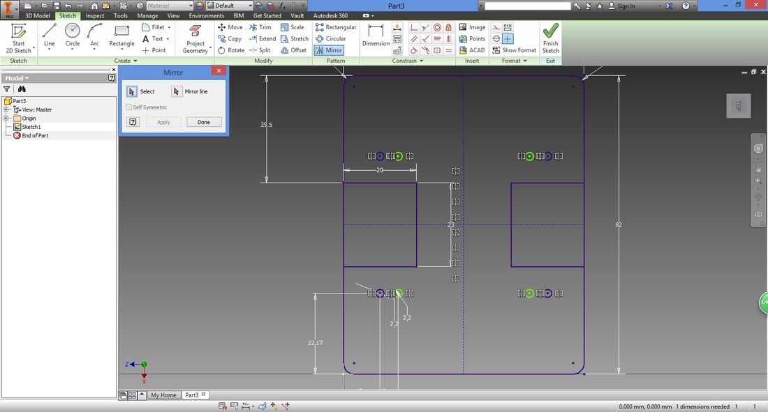
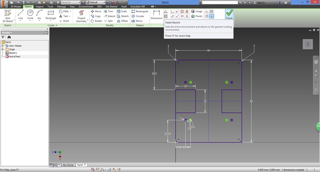
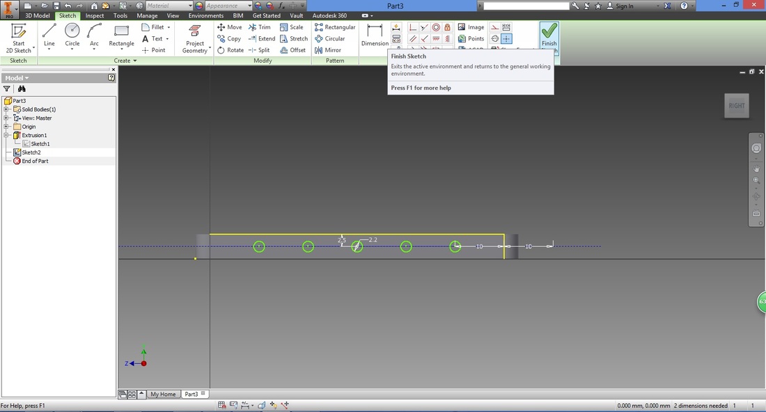
step 11Once the sketch is complete, select Finish.
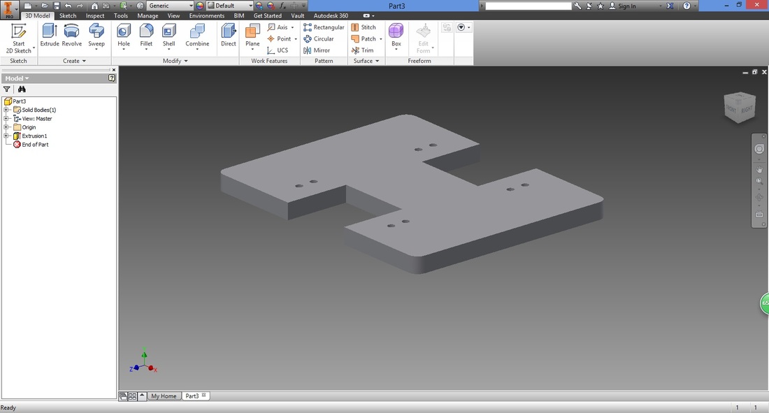
Step 12The view will be rotated back to the default view.
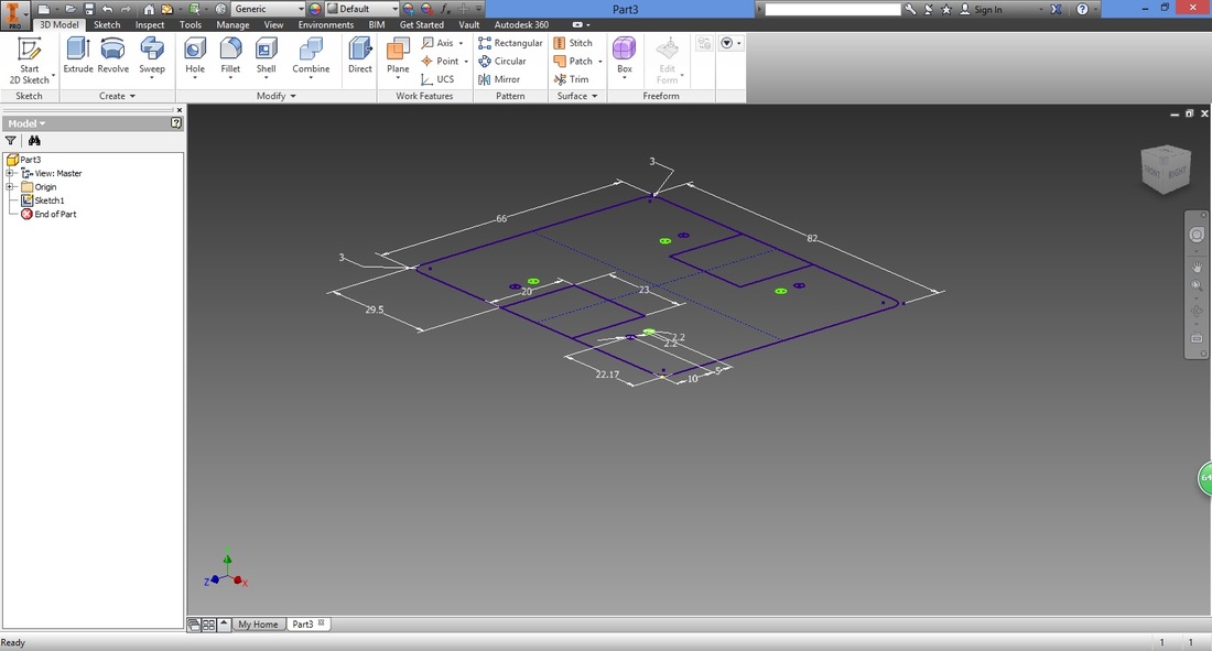
Select Extrude function to change the 2D sketch into a 3D part.
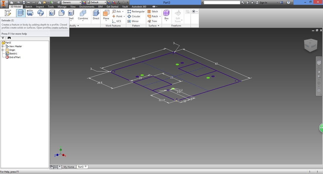
Highlight the selected region by hovering over it.
Note that the region cannot be highlighted if it is open (gap between points). 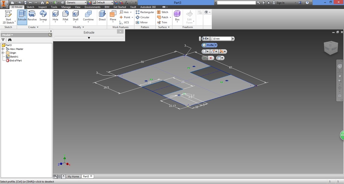
Left-click the region. You can then extend it either by moving the cursor upwards or downwards, or typing in the desired thickness.
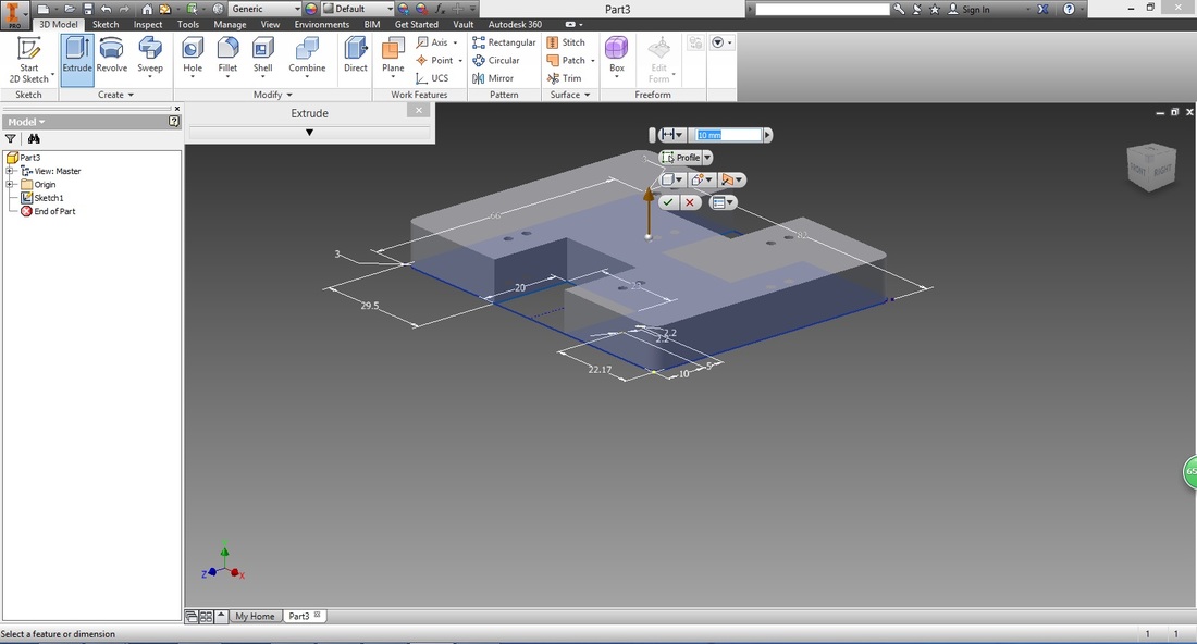
Press Enter.
Step 13Next, select the next surface you want to sketch on. It will be highlighted as shown below.
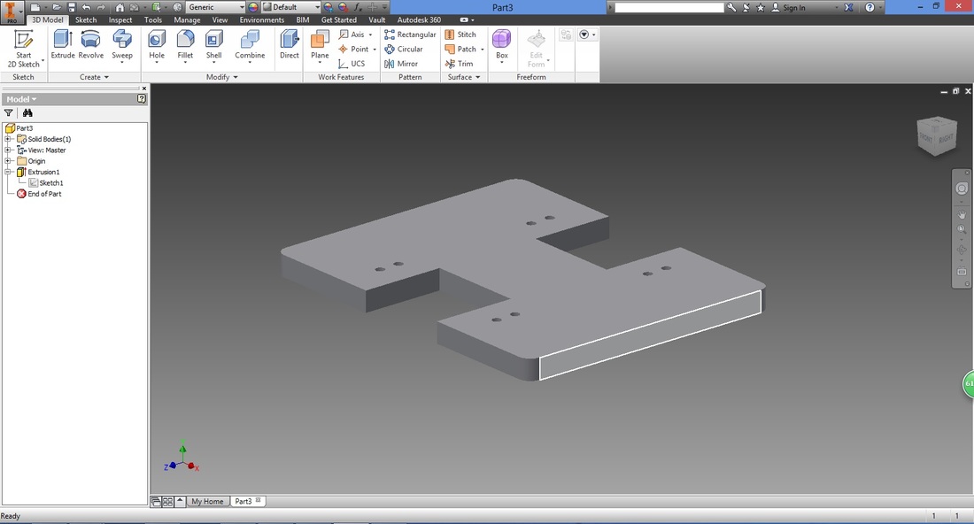
Select Create Sketch option.
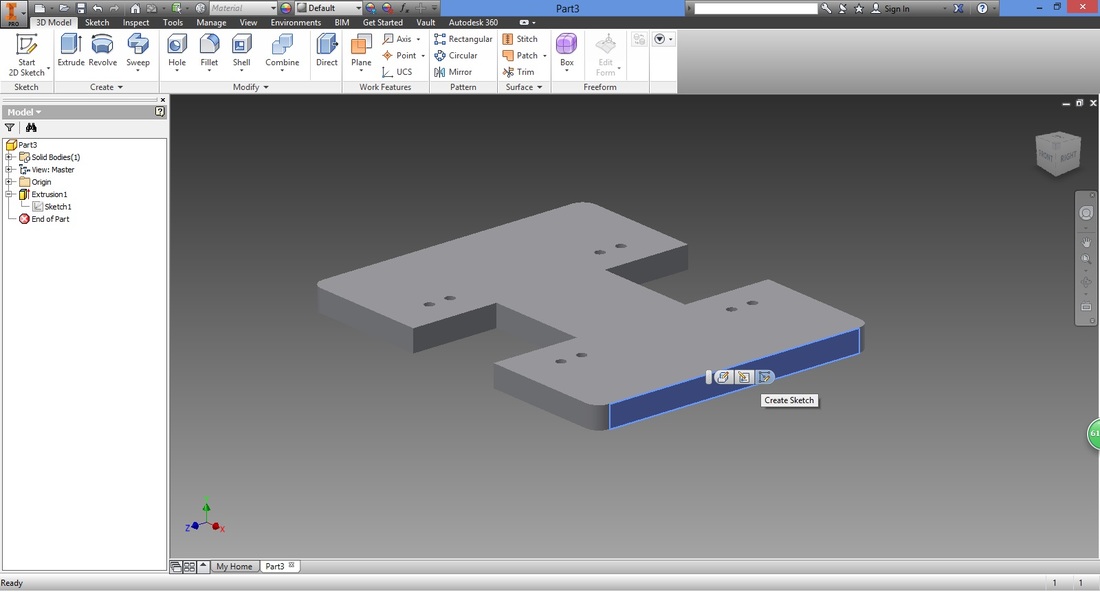
The view will be rotated to face you.

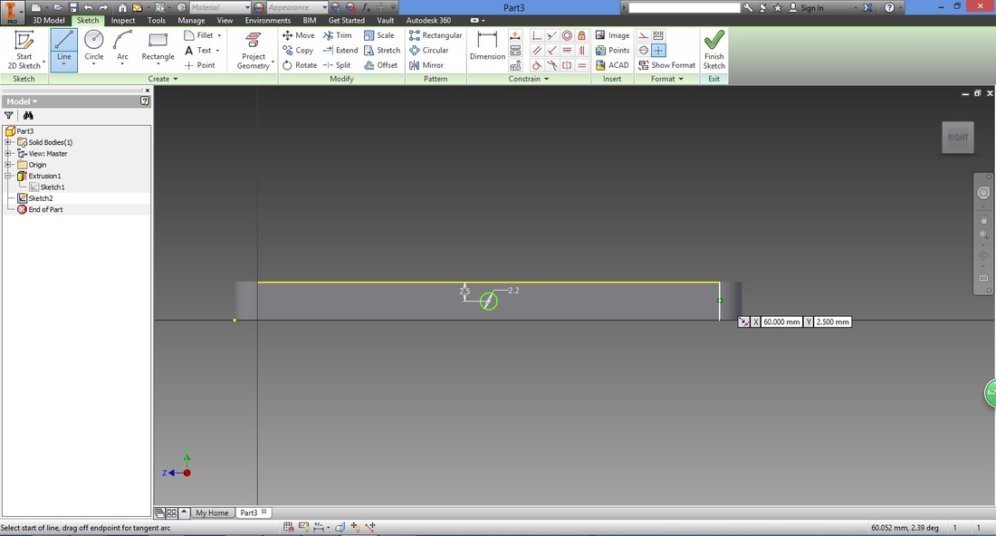
Using the Line function, draw a line for the top horizontal line.
Select the Circle function and trace the midpoint of the top horizontal line. Left-click within the thickness. 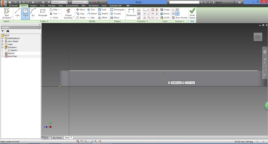
Type in the radius of the circle.
Similar to before, I used a 1.1mm Radius as I intend to use m2 screws. 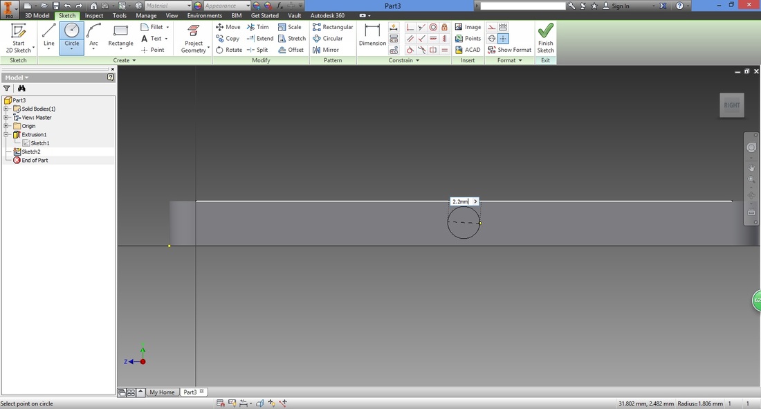
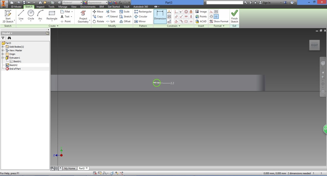
Select the Dimension function and position the circle accordingly.
Next draw a line using the Line function to trace the vertical line on the right.
Repeat on the left vertical line.
Connect the midpoint of both vertical lines together. 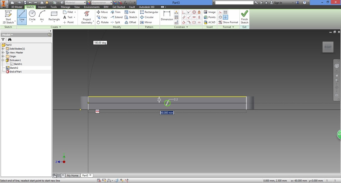
Change this to a construction line. (Right-click the line)
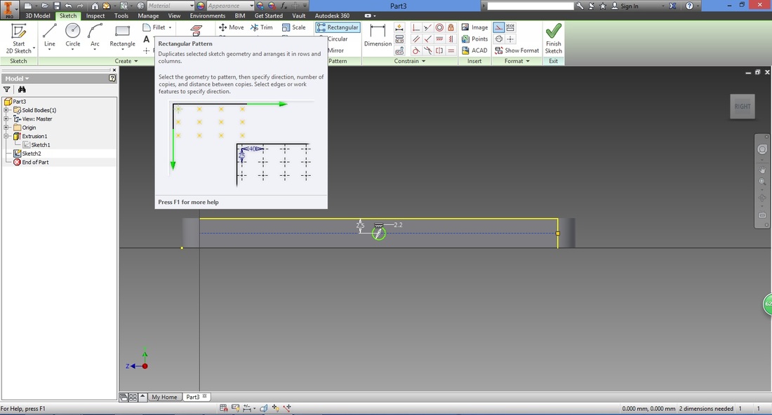
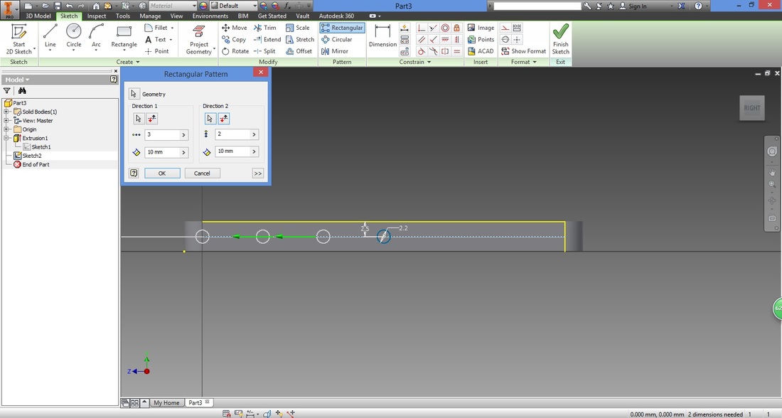
Select Rectangular pattern function, to produce copies of a selected part vertically or horizontally.
In the Rectangular pattern window, Geometry should be selected.
Select the circle drawn. 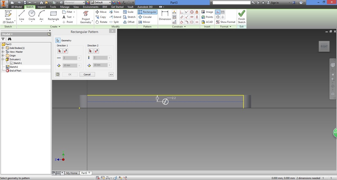
Select cursor under Direction 1 in Rectangular Pattern window and select the construction line created.

Set the number of copies (includes original) required in the Rectangular pattern window and distance between copies.

Select cursor in Direction 2 and change settings accordingly in the window.
Note that Direction 2 here should be pointing away from Direction 1.
Select Flip in Rectangular pattern window to flip the direction opposite. 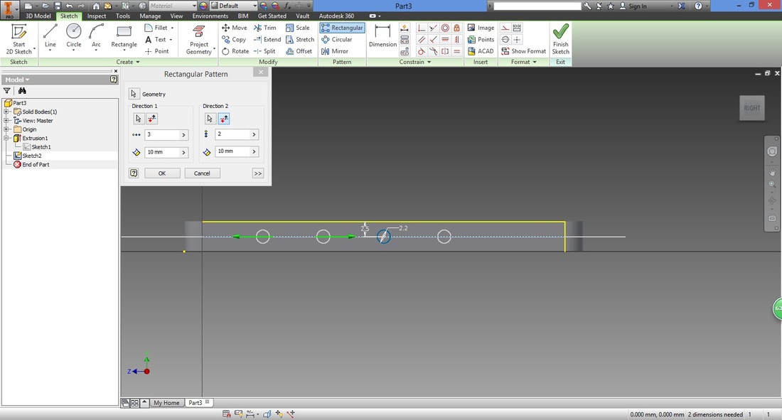
Set the number of copies (includes original) required in the Rectangular pattern window and distance between copies for Direction 2.
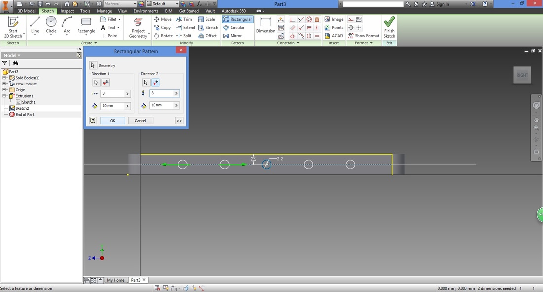
Once settings are done, select OK.
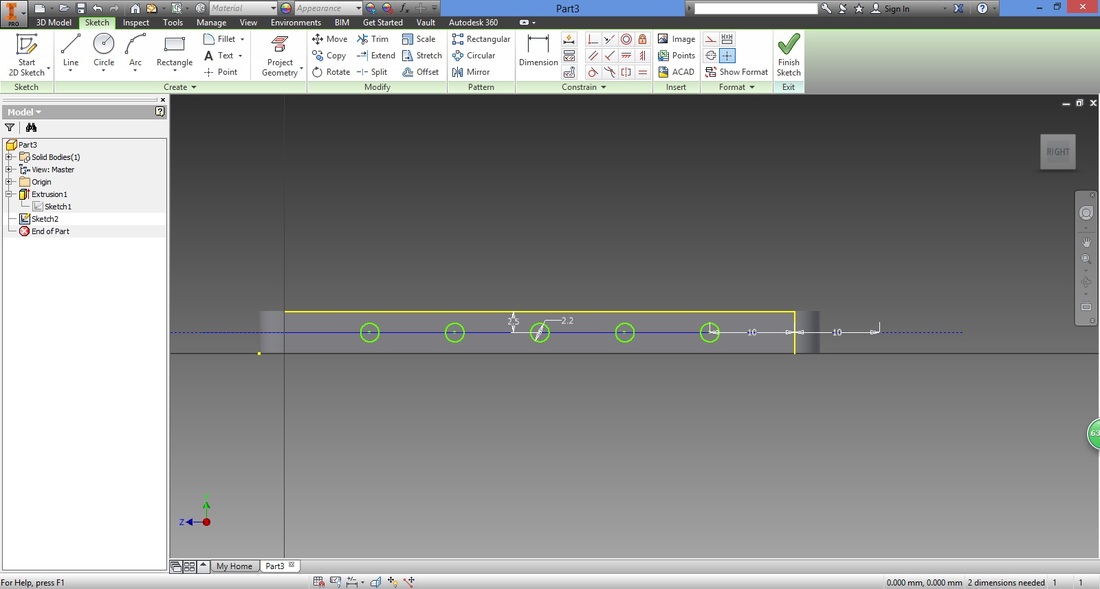
Select Finish to close sketch.
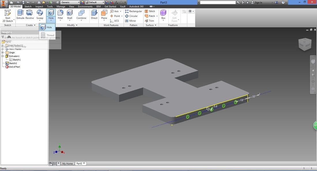
step 14Select Hole function from 3D Model ribbon.
Set the following settings.
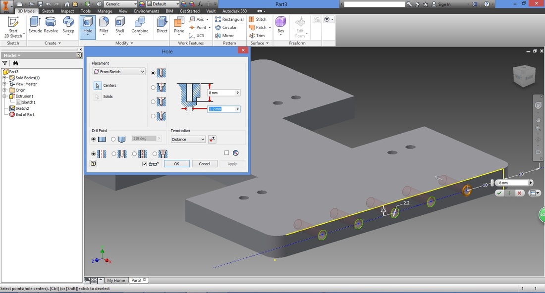
As this part is intended to be 3D printed, printing of threads may not be possible depending on the accuracy of your printer. Click Centres in Hole window and select centres of 5 circles. The preview will be shown if you check the glasses symbol in the Hole window. 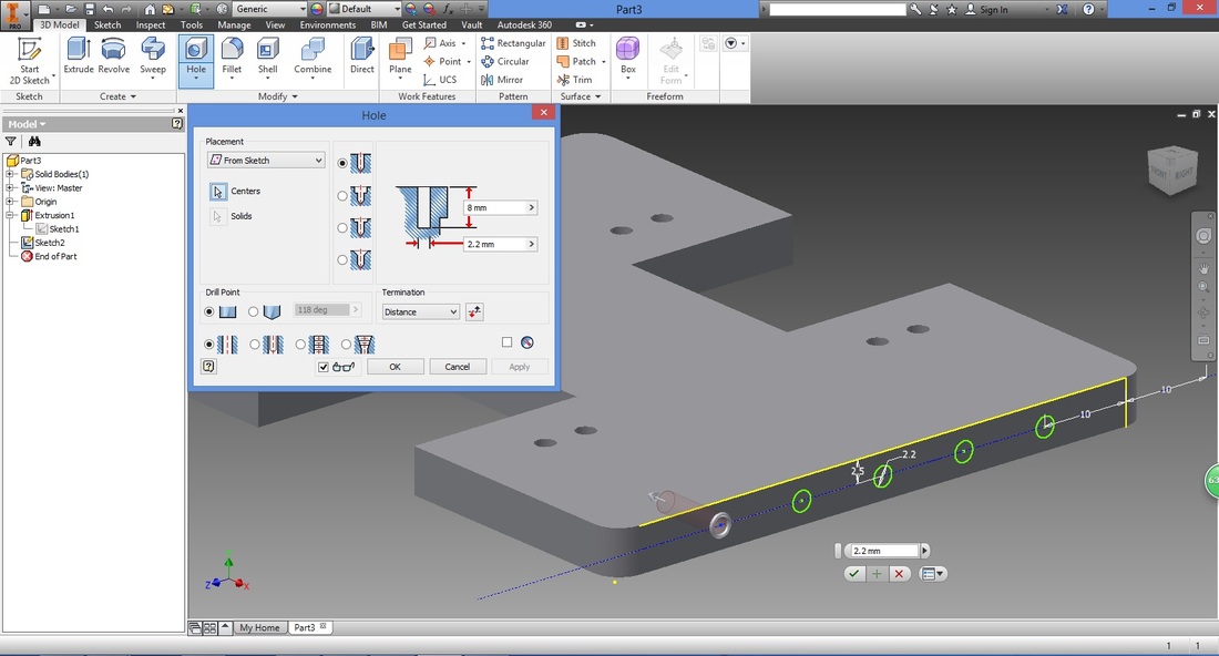
Once done, select Apply and then OK.
Note that by highlighting a feature or sketch in the left panel, will highlight the respective part of your model. 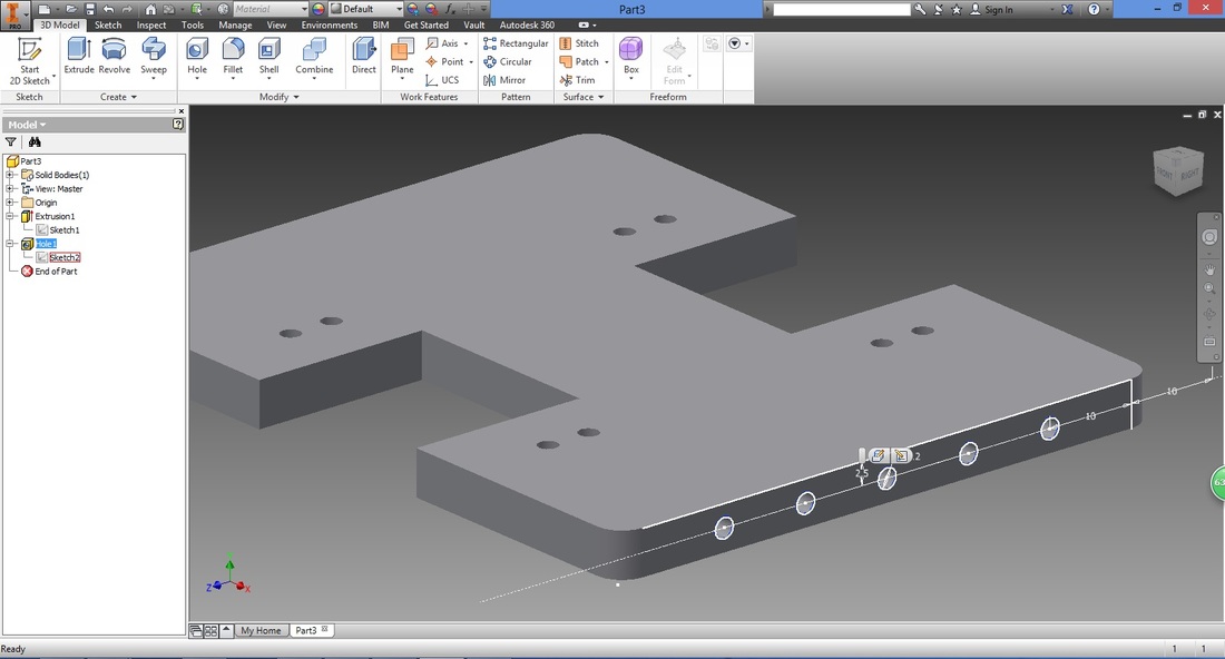
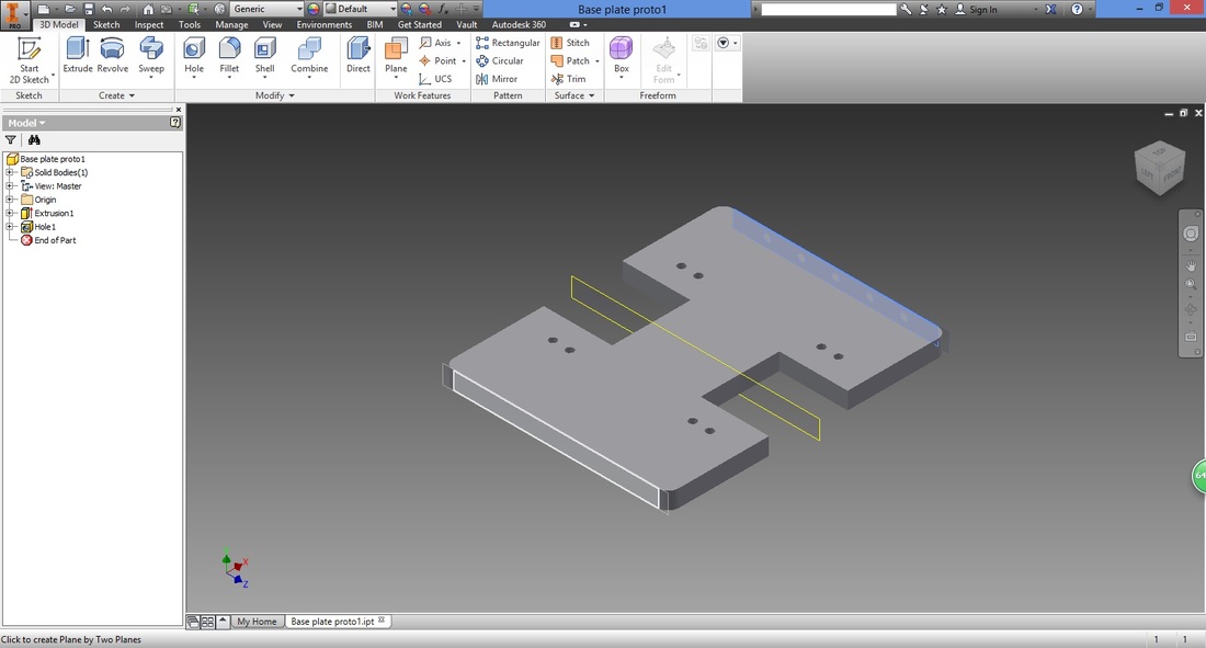
step 15Next, we create a plane to mirror the Hole 1 feature. Select Midplane between Two Planes function.
Note that the features require a plane to mirror across rather than a line. 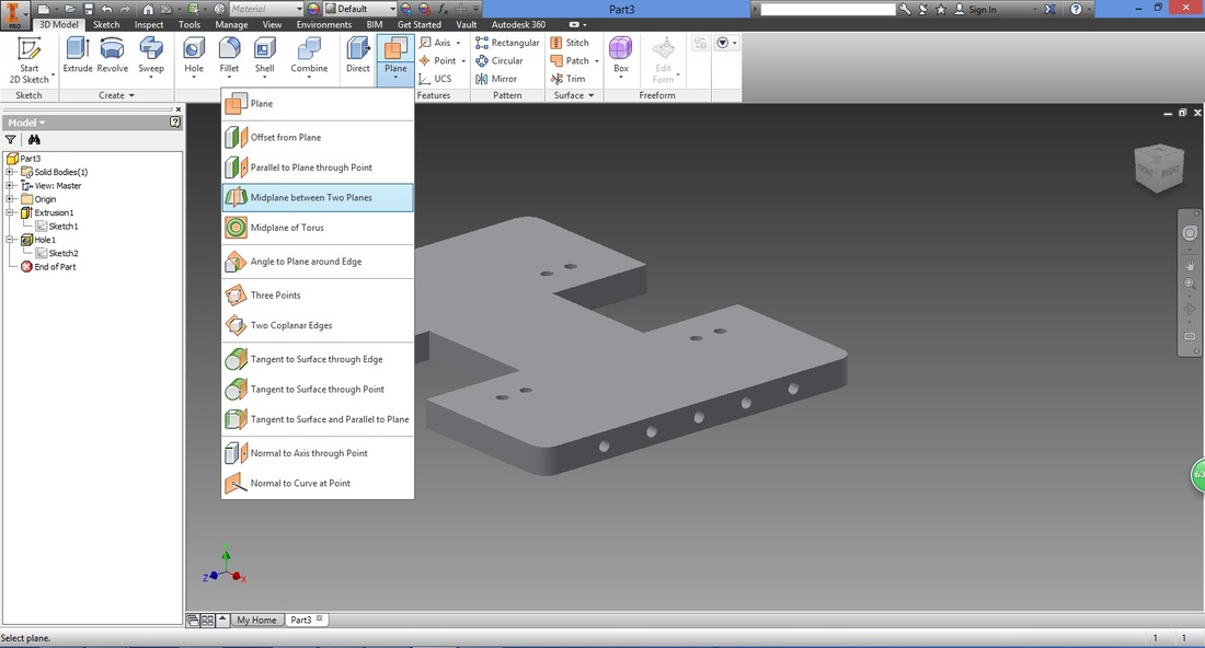
Select the first plane where you sketched the 5 holes.
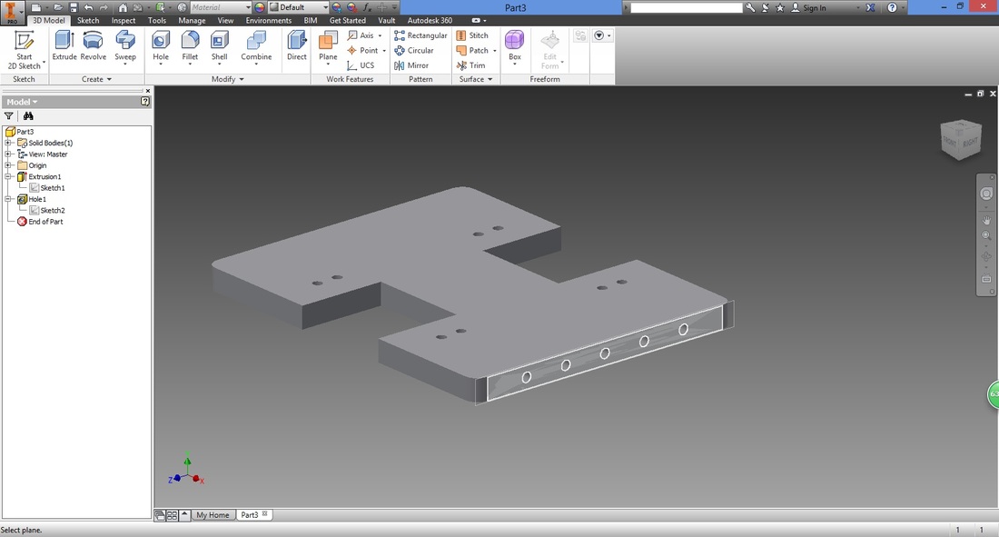
Next rotate the view to the opposite plane.
Do so by selecting the corner (shown below) on the cube in the top right of the screen. 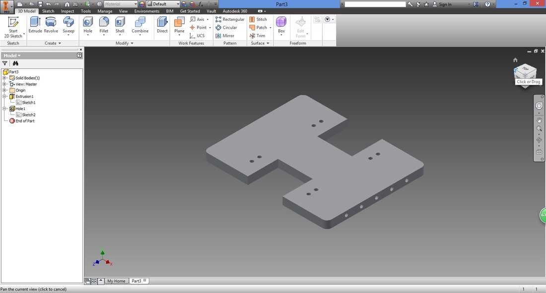
Select the opposite plane. The midplane (in yellow) will then appear.
step 16Select Mirror function.
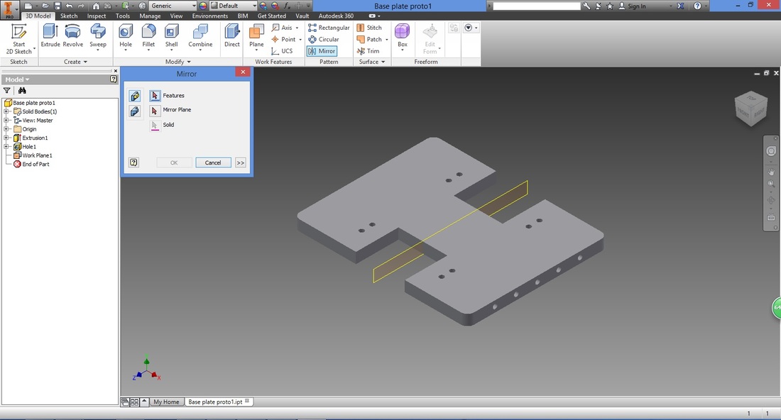
Make sure Features in Mirror window is selected.
Select Hole 1 features by selecting the 5 holes, or 'Hole 1' in left panel. 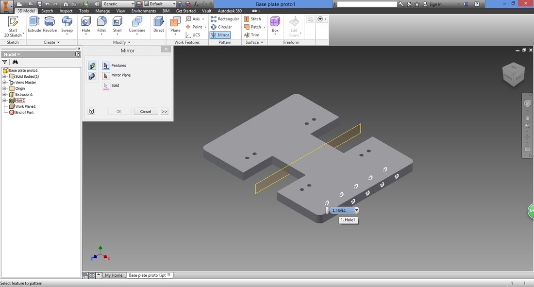
Select Mirror Plane in Mirror window and choose Work Plane 1 (the mid plane created).
Select OK. 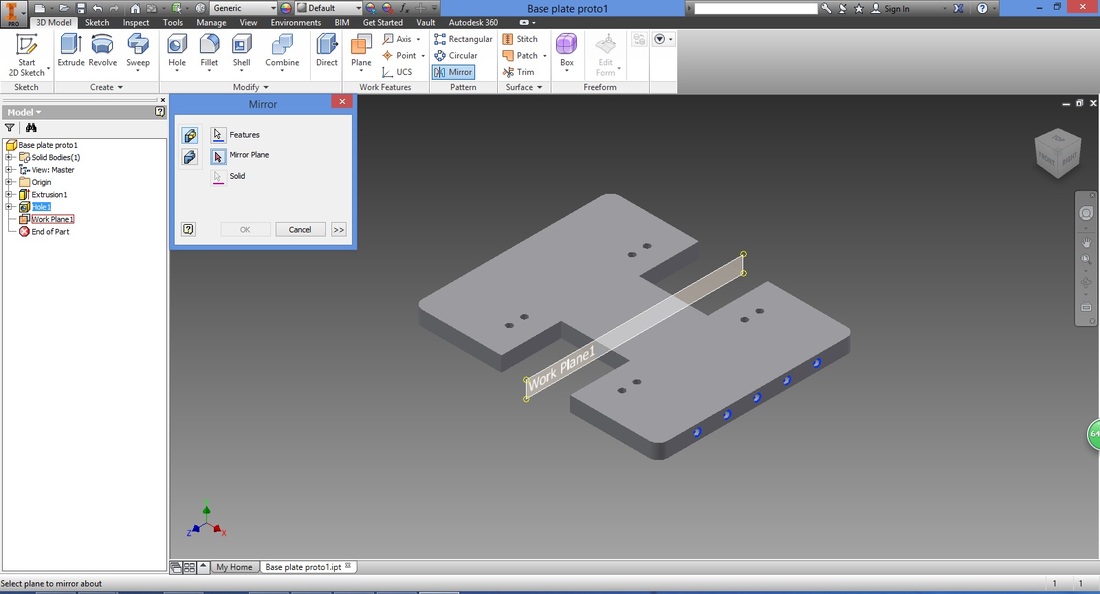
The mirrored feature will now be shown. You may rotate the view to double check.
To hide Work Plane 1, right click 'Work Plane 1' in the left panel and un-check Visibility.
You may check Visibility later on if you wish to show the feature. This applies to other features and sketches as well. 
first phase completeCongratulations! You have now completed the very first phase.
second phaseYes, we know that you can actually do this section in the first part (before Step 12), however this phase will give you the experience on how to go back to the sketching board to edit your part rather than start from scratch.
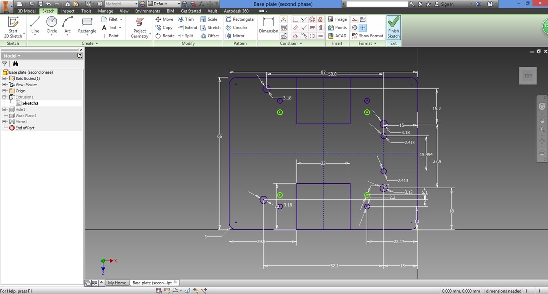
This section will teach you how to put in the remaining holes for the other components. You should be able to complete this easily after having gone through first phase. Step 17From the Model Panel on the left, expand Extrusion 1, and right click the Sketch.
Select Edit Sketch. 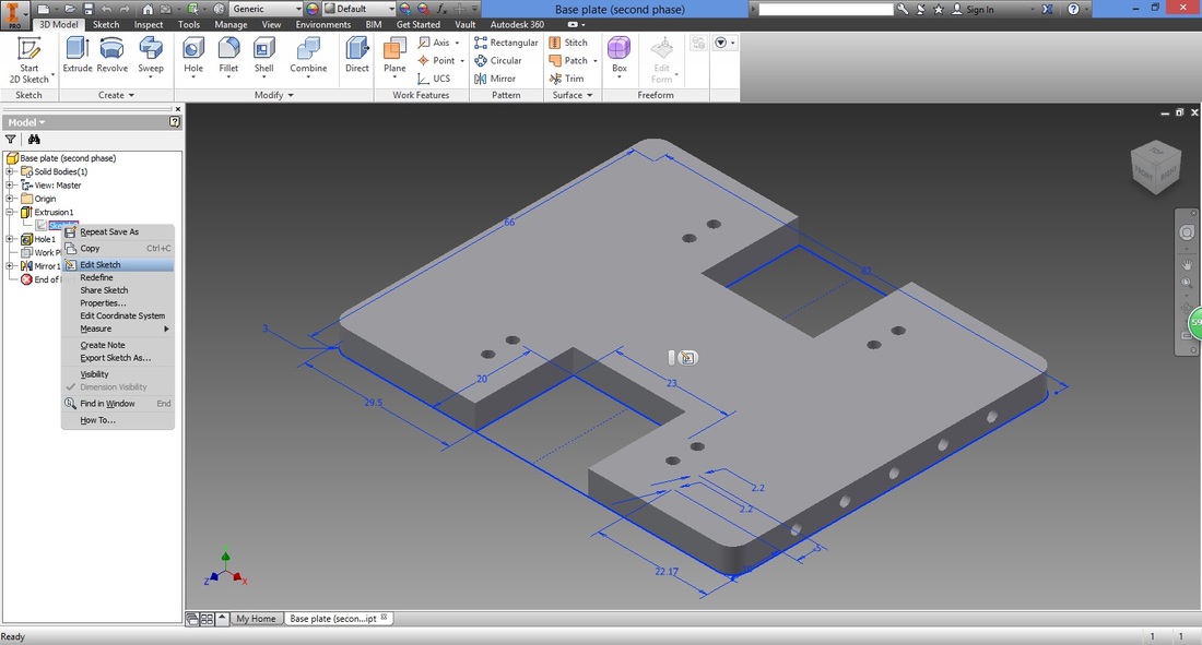
You will see this.
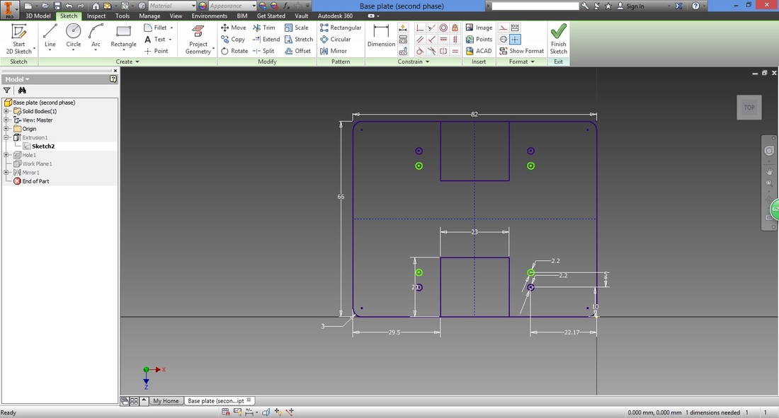
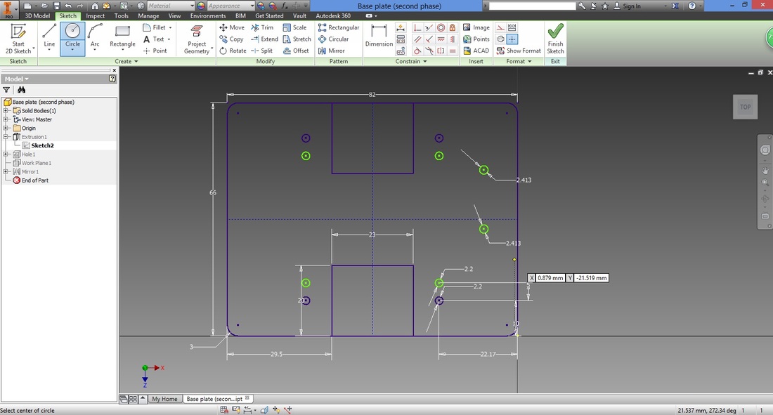
step 18Select the Circle function.
Select any area within the top right region.
Type in the radius of the circle. THE DIMENSIONS OF THE HOLES HERE ARE BASED ON THE SCREW SIZE required by the Ball Caster with 3/4" Metal Ball. MODIFY IT BASED ON YOUR REQUIREMENT. 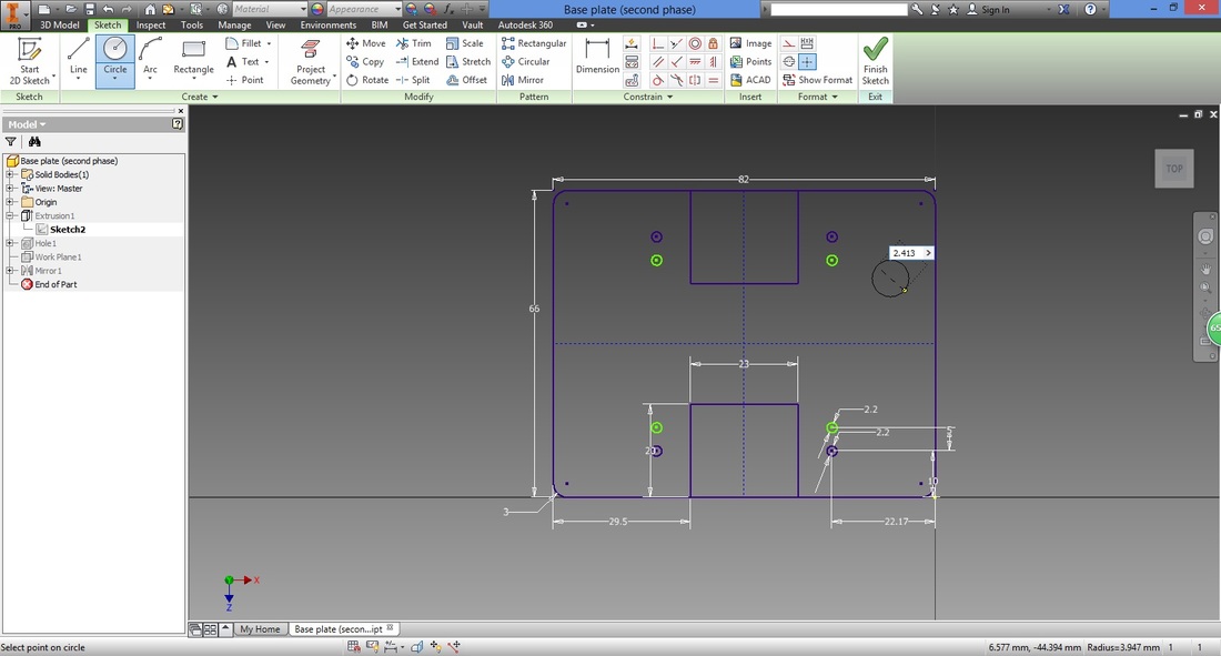
The circle will appear as shown below.
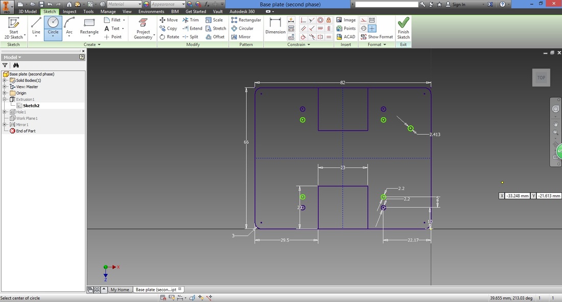
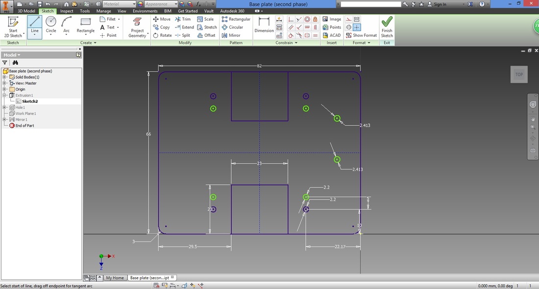
While in the Circle function, hover cursor over centre of circle and trace down. This is to ensure the next circle drawn has its centre aligned with this circle.
Trace below the mirror line and create a circle with the same radius. 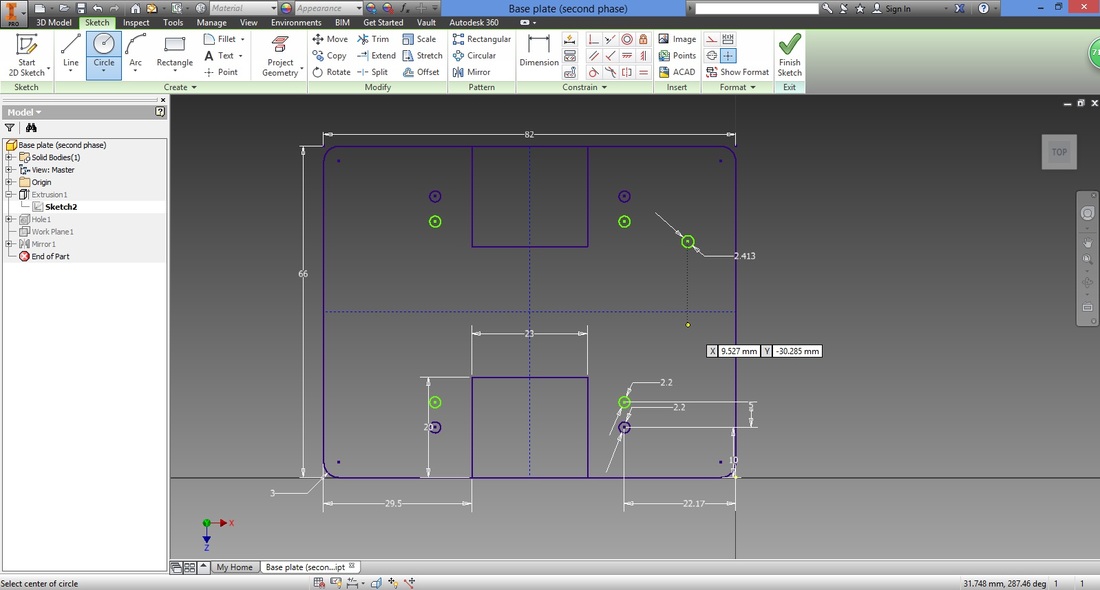
Select Line function.
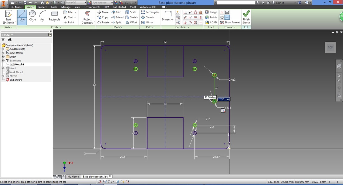
Create a line between the centre of the first circle and the mirror line.
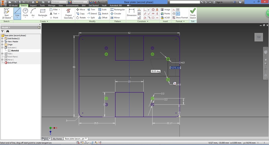
Create a line between the mirror line and the centre of the second circle.
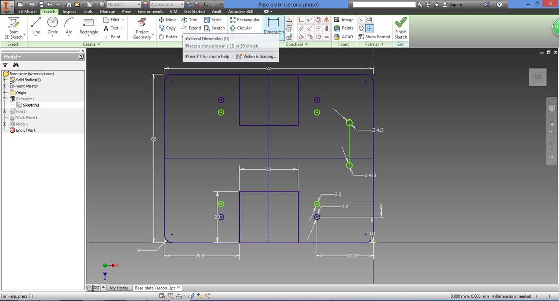
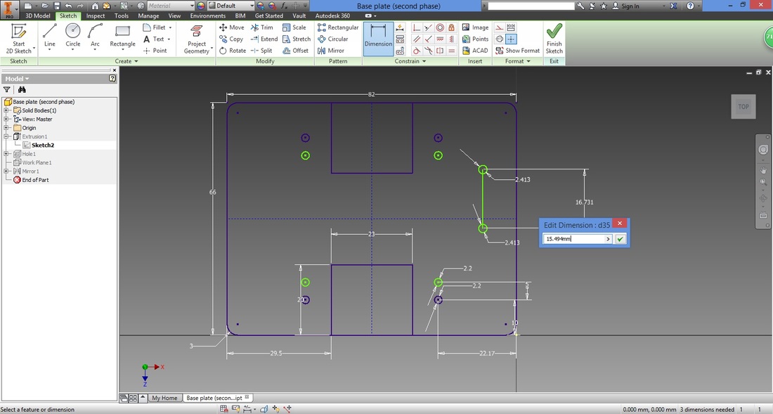
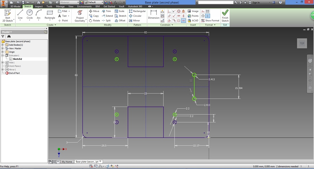
Next, select the Dimension function.
Select the centres of both circles and fix the distance between both circles.
Select the Equal function.
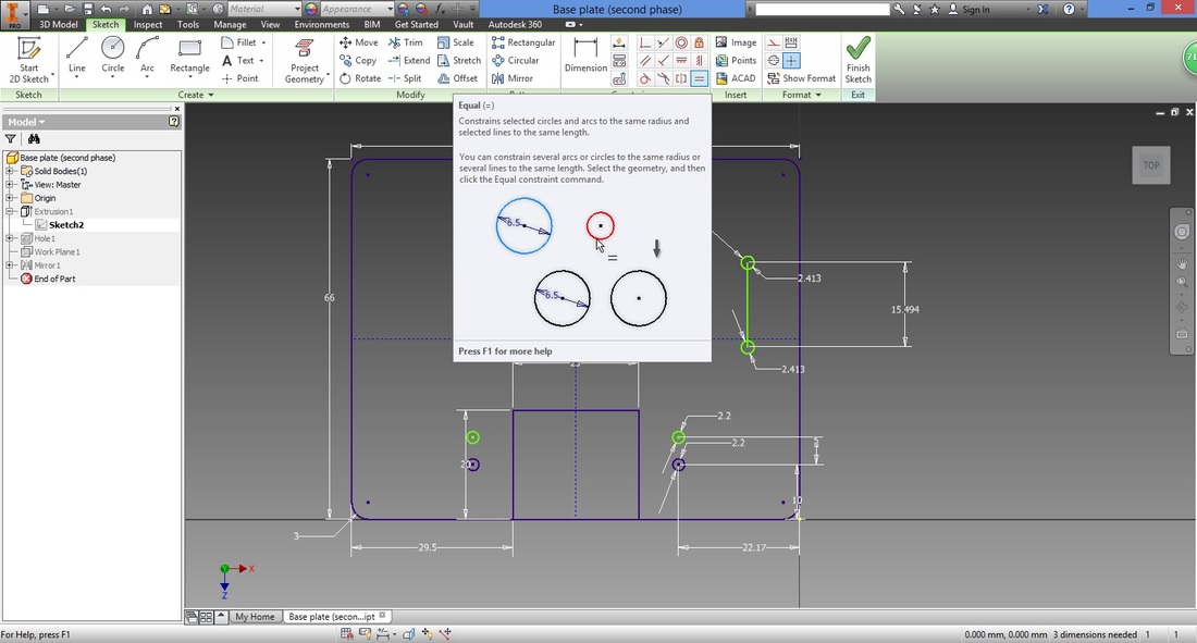
Select the line between the first circle and mirror line.

Select the line between the mirror line and the second circle.
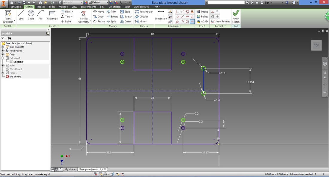
Distance of both circles to the mirror line will automatically become equal.
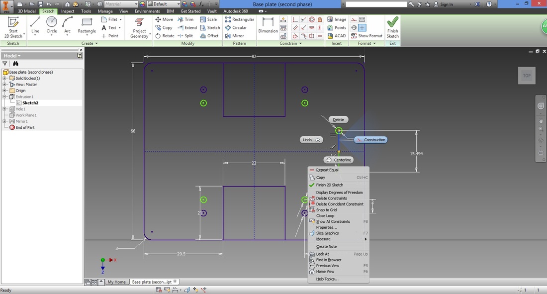
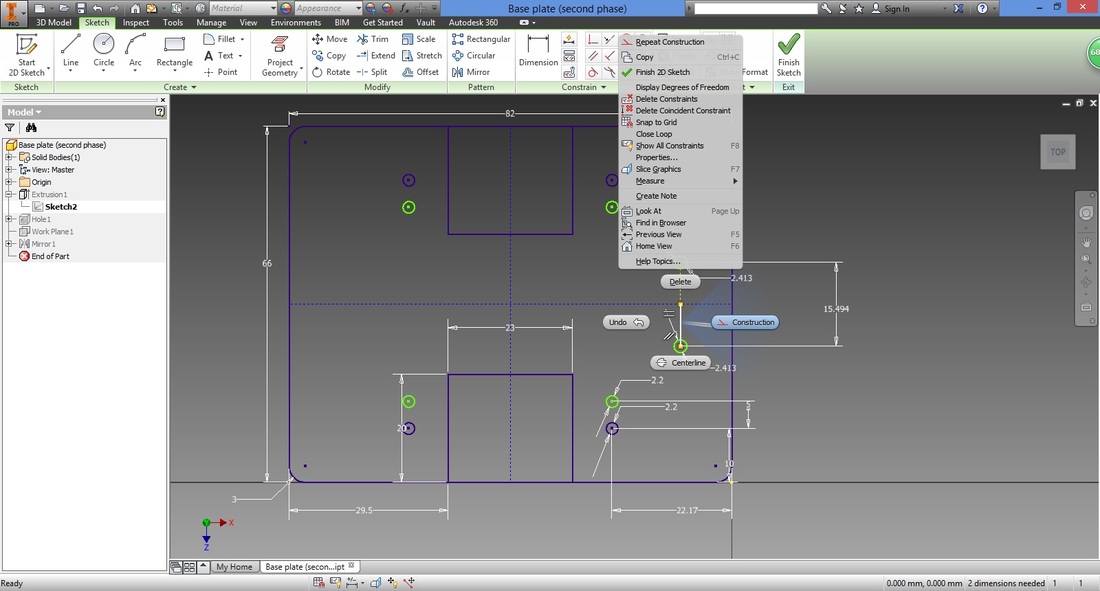
Change both lines connected to the mirror line into construction lines by right clicking the respective lines.
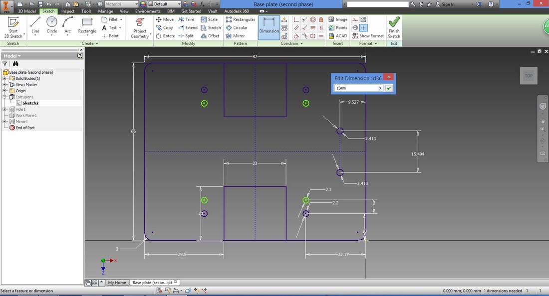
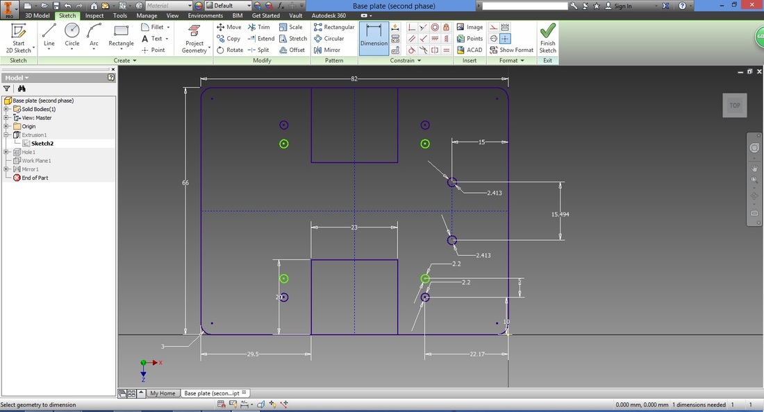
Select the Dimension function.
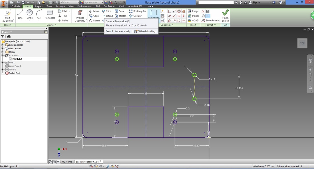
Key in distance desired between holes and edge of base plate.
The two holes to incorporate the ball caster with 3/4" metal ball have now been incorporated.
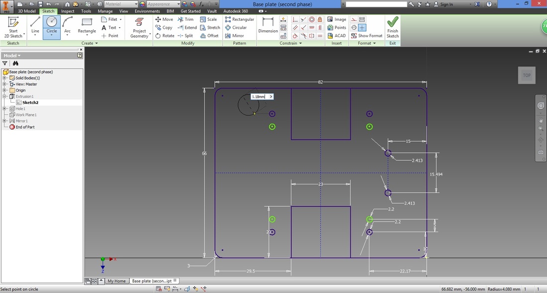
step 19Select the circle function.
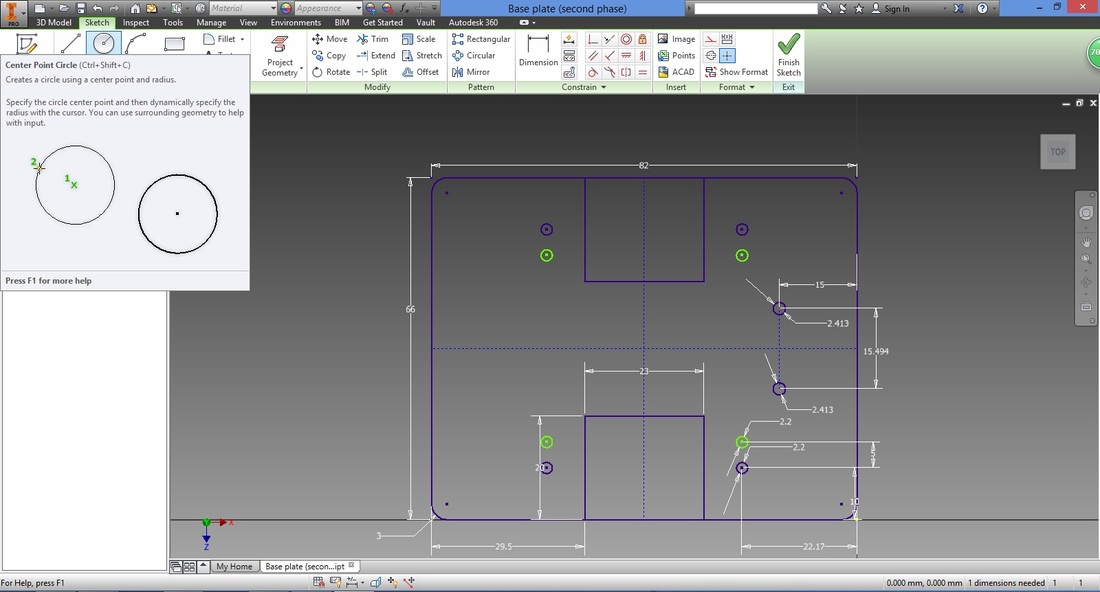
Similarly, create a circle and fix the diameter at four corners of the base plate.
Ensure that the circles have the same diameter. Next we will dimension their distances accordingly.
THE DIMENSIONS OF THE HOLES HERE ARE BASED ON THE spacers which will hold the arduino uno. Its distances are based on the arduino uno board. MODIFY IT BASED ON YOUR REQUIREMENT. 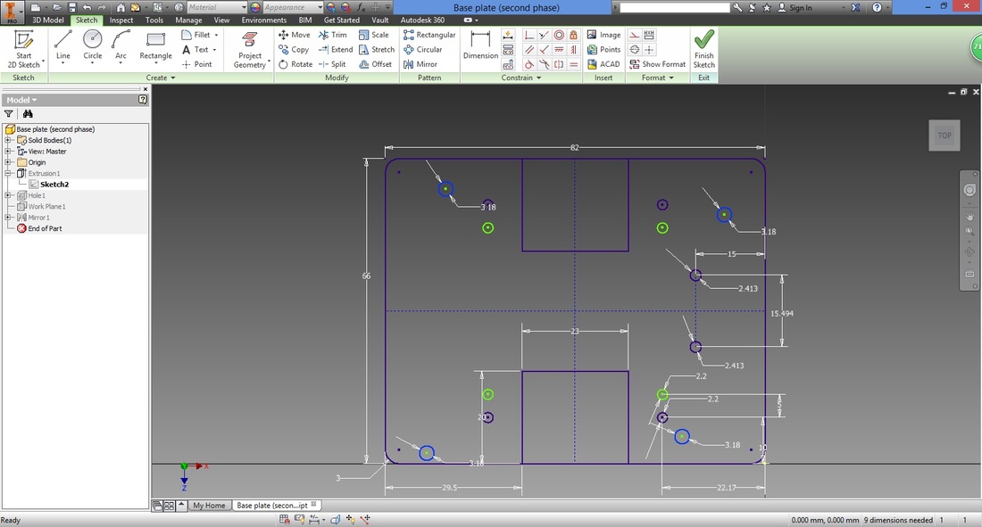
Next, we align the two holes on the right.
Select Vertical Constraint function. This function allows two points or lines to be aligned vertically on the same line. 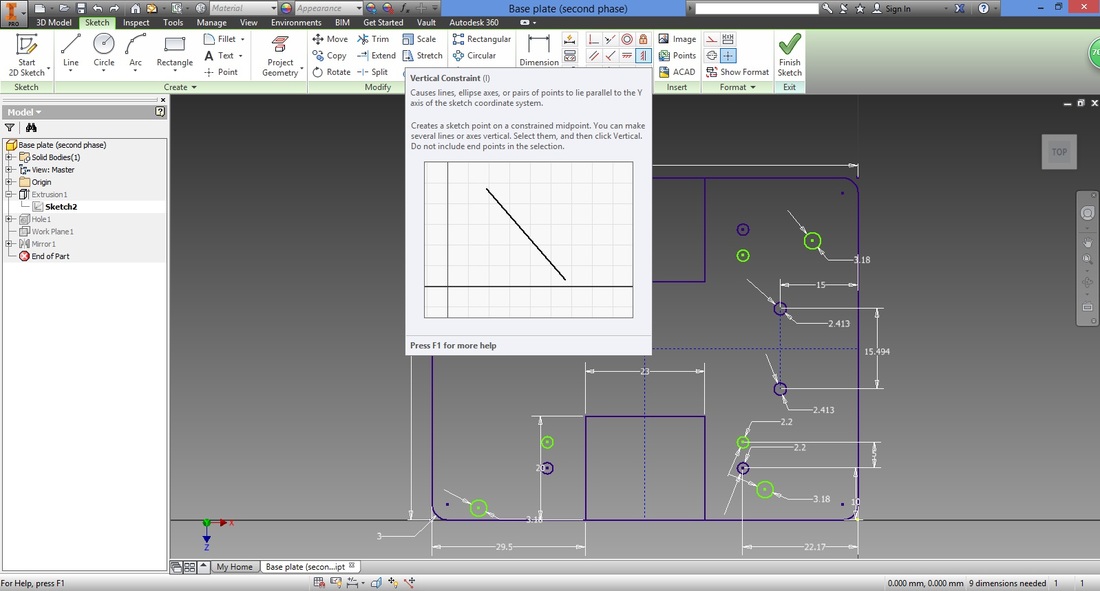
Select the centre of one of the holes in the right top region.
Select the centre of the remaining circle (right bottom region).

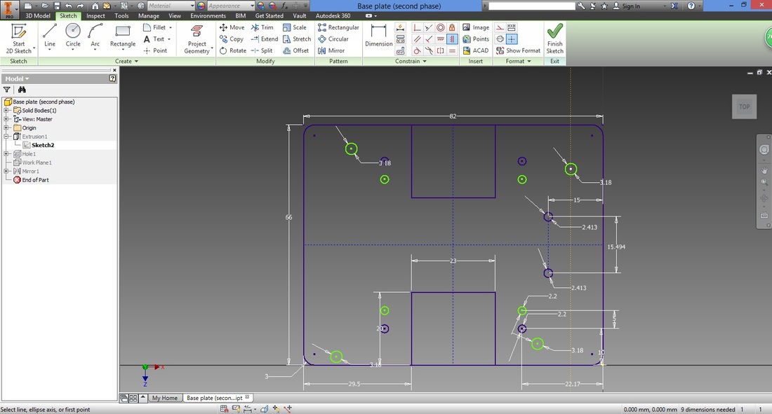
Both circles will be aligned.
Next, select the Dimension function. 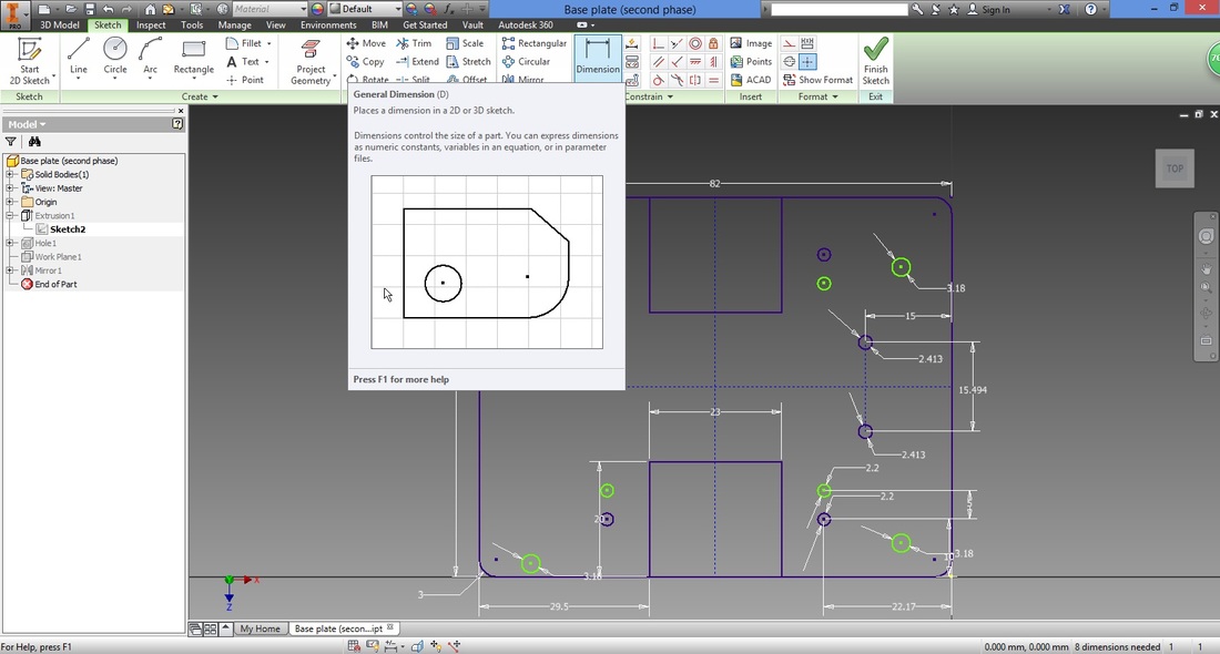
If you modify the dimensions to that of what you require, do ensure they are defined well.
Select Finish to complete sketch.
Under the Model Panel, right click Extrusion1 and select Edit Feature.
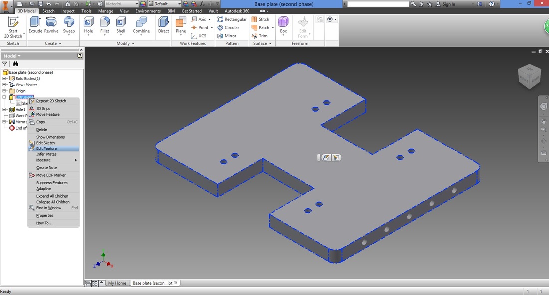
Rotate the view to see the sketch below.
You can either click the viewing cube in the top right corner or hold Shift on your keyboard and rotate using the scroll button on your mouse. 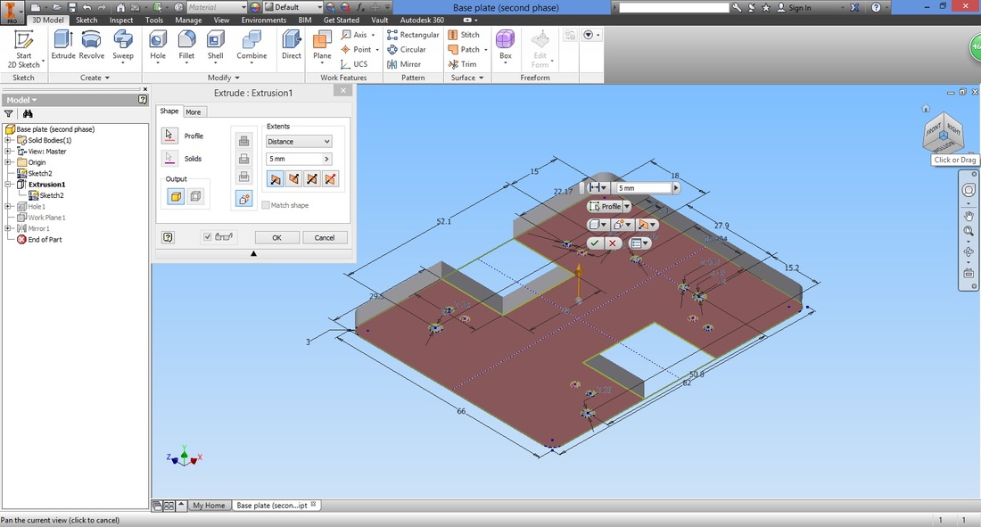
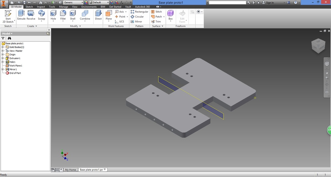
Select "Profile" inside the Extrude window.
Next, hold Ctrl on your keyboard and left-click the previous profile to deselect previous profile. Areas you want to extrude should be highlighted in red. LEFT-CLICK to select 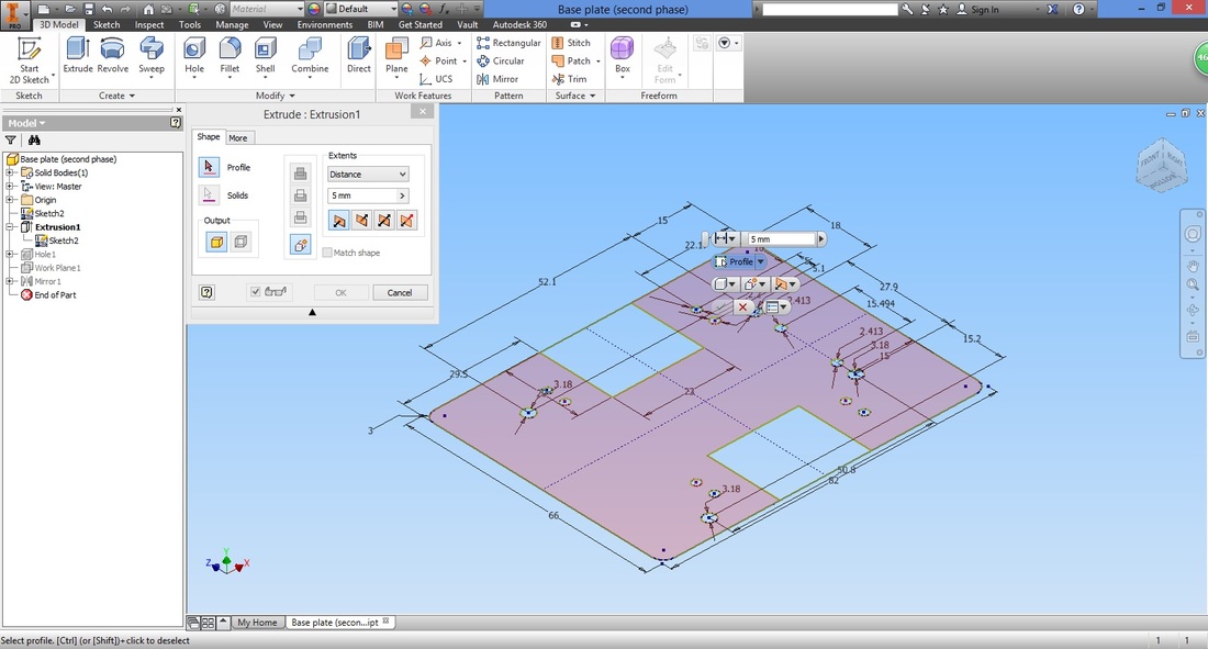
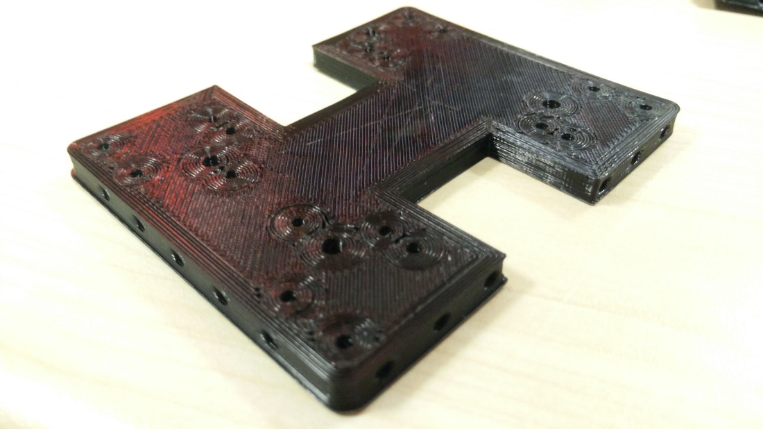
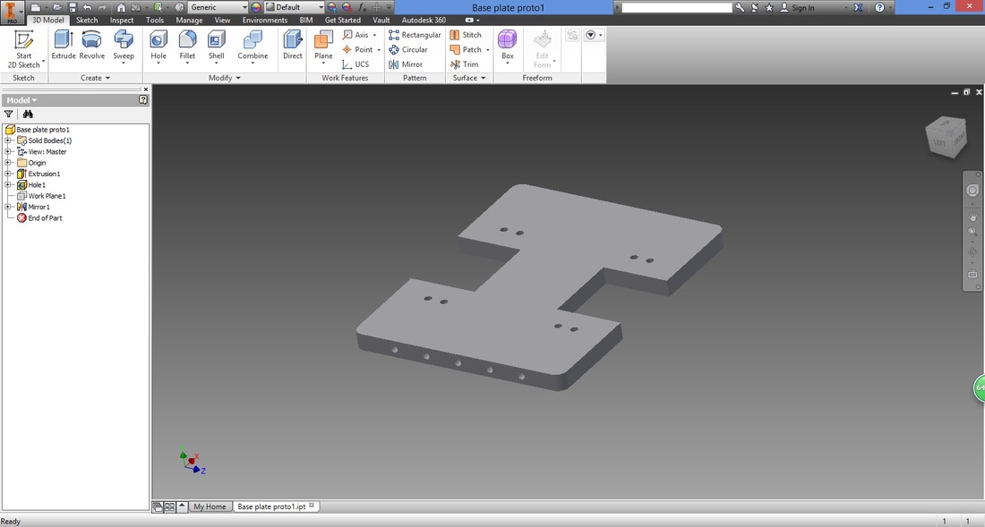
cONGRATULATIONS! yoU HAVE NOW COMPLETED THE BASE PLATE!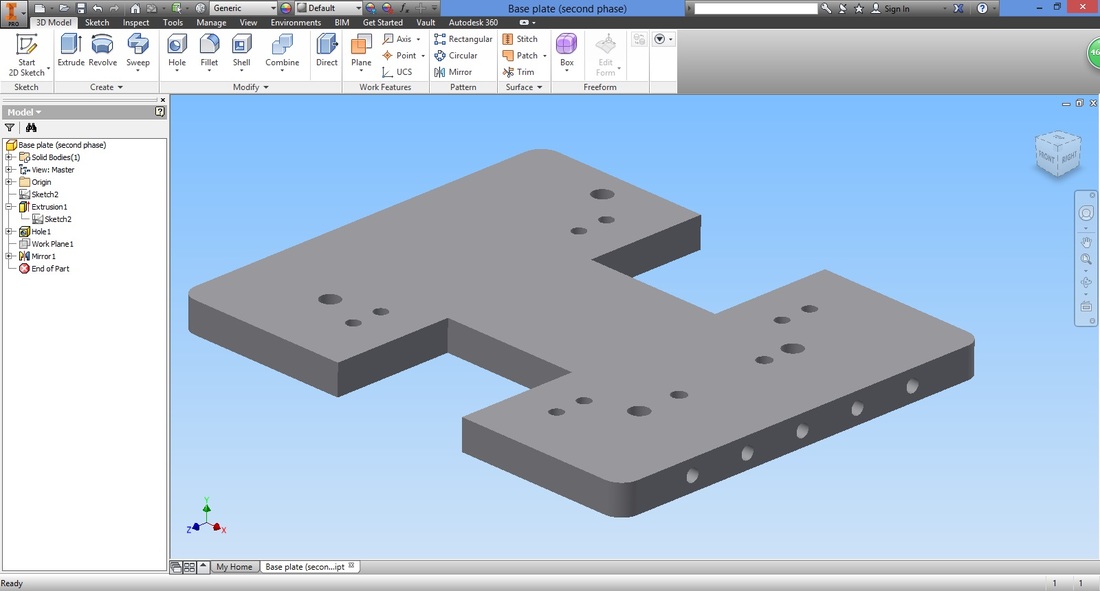
| ||||||||