|
The following is a tutorial to teach you step by step how to create an L-Bracket using the educational version of Autodesk Invertor Professional. If you have yet to install it, you may refer to the link below.
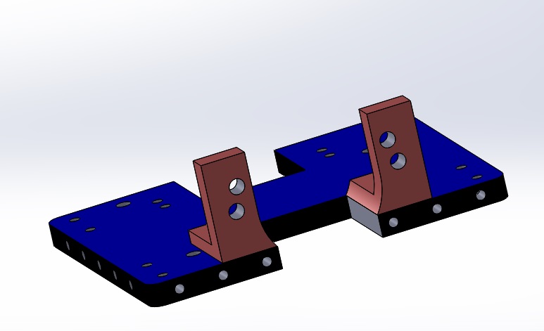
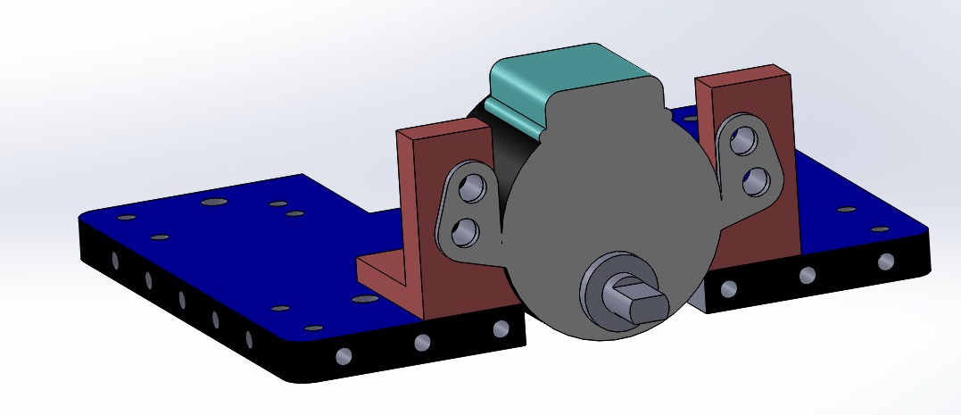
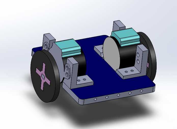
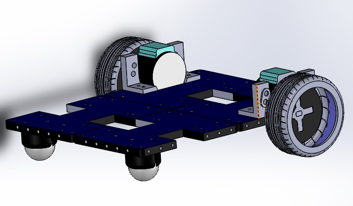
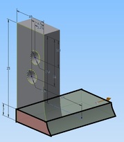
This base plate dimensions were drafted in consideration of the following components:
Here's a few good things to remember before we begin:
As this serves as a tutorial, there are intentional hiccups along the way to give you a better learning experience of what to look out for in the future.
LET'S START!STEP 1Launch Autodesk Inventor Professional.
The homepage will appear as shown below. Select PART to create a new part. WHAT IT MEANS: 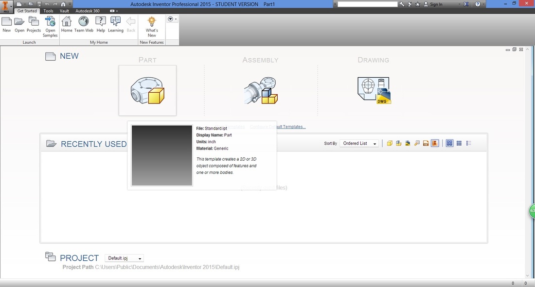
STEP 2 (IMPORTANT)A good habit to have is to check and set the dimensions of your drawings.
Under the Tools ribbon, select Document Settings. 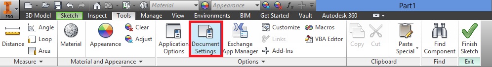
A window will then appear.
Select the Units tab, and adjust accordingly. 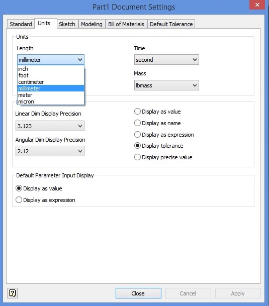
Select Apply then Close, to apply settings.
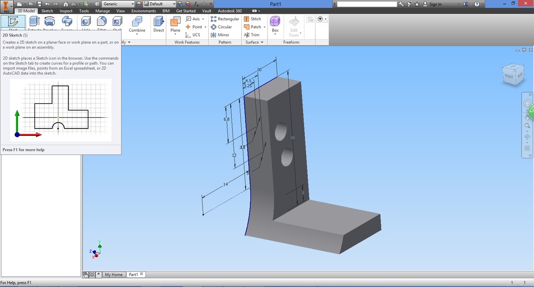
STEP 3In the 3D Model ribbon, select "Start 2D Sketch".
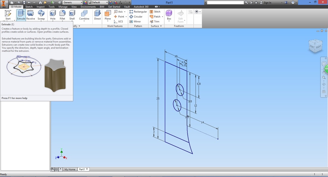
Notice that if you hover over the function for long, a quick introduction of the function will appear. 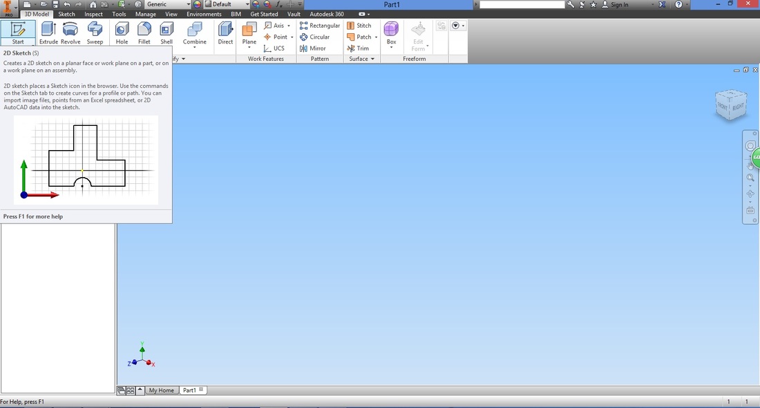
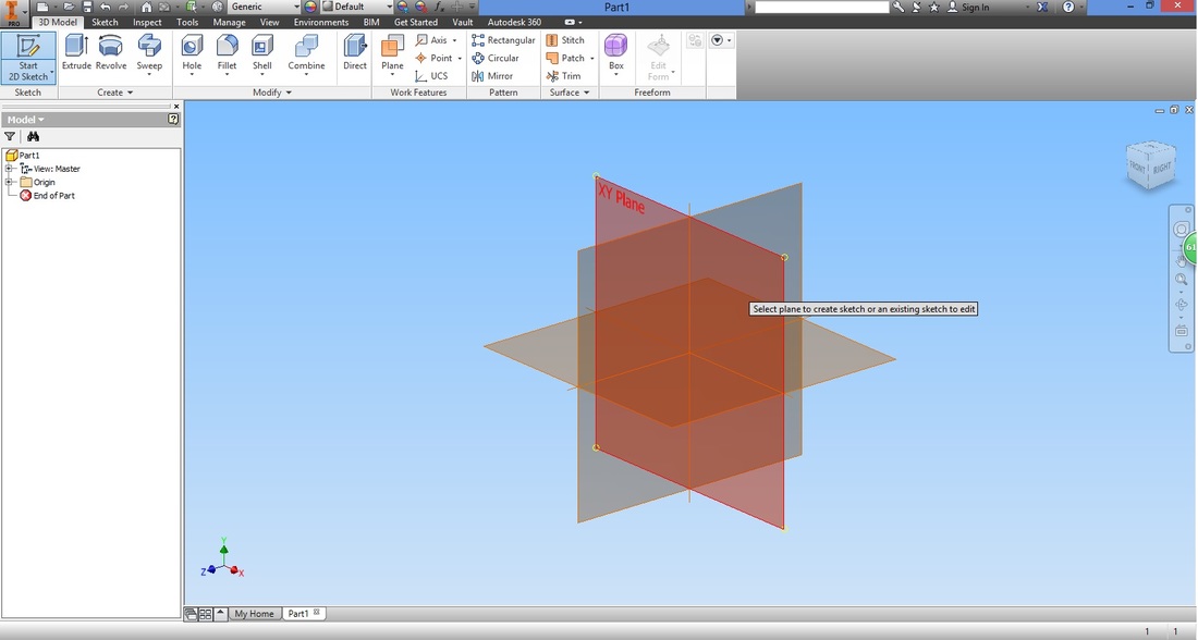
Next, select the plane you would want to draw on. Here I've selected the XY Plane.
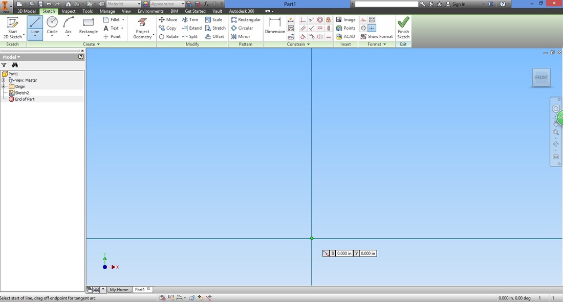
WHAT beginners SHOULD KNOW: STEP 4From the Sketch ribbon, select the Line function.

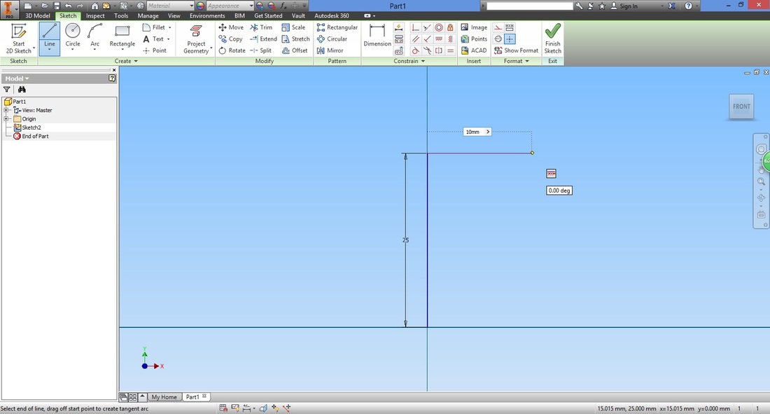
Hover over the origin, and when the circle turns green, left click it. This gives you the first point of the line.
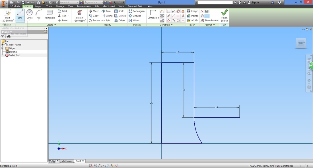
Type in the desired length of the line. This will determine the height of the L-Bracket.
Notice that the angle of the line is shown (90 deg here) 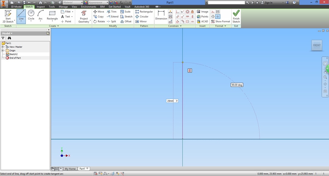
The Height of the L-Bracket was determined by how high we want to lift the motor and also the base plate. Without exiting (pressing ESC), draw a horizontal line.
Draw another horizontal line from the origin.

Next we draw another vertical line.

Next we draw a line for the centre of the circle.
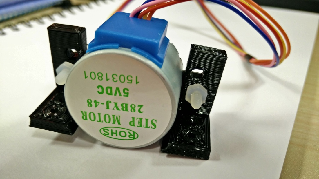
Here I used the radius of the BYJ48 Stepper Motor of 14mm. As the motor is circular, a Circle is used to give the L-Bracket the curvature required to hold the motor. 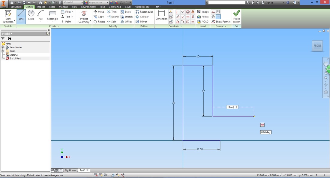
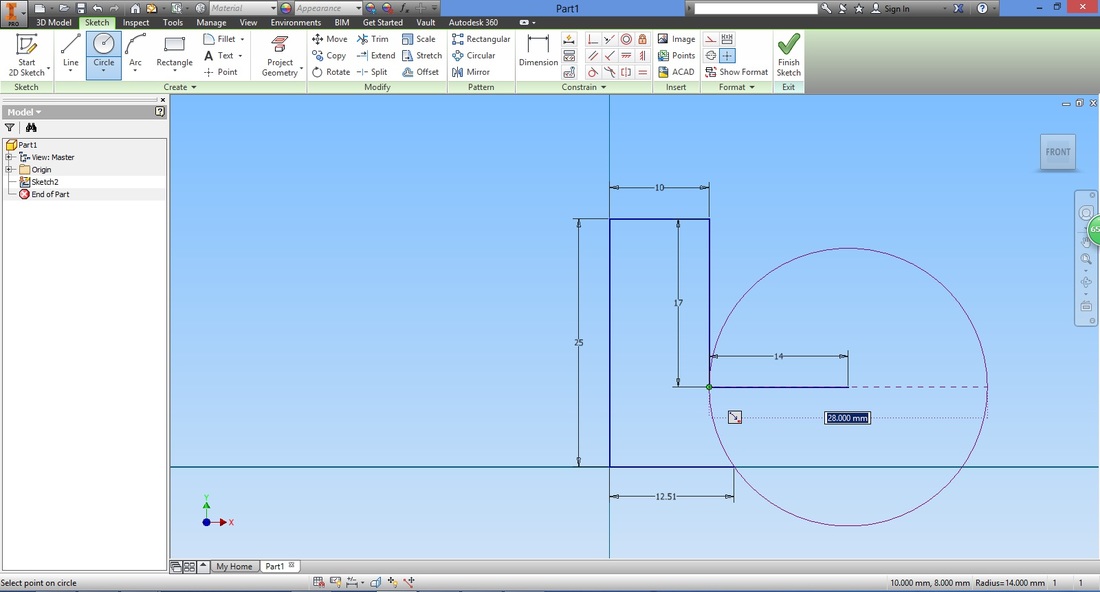
STEP 5Select the Circle function.
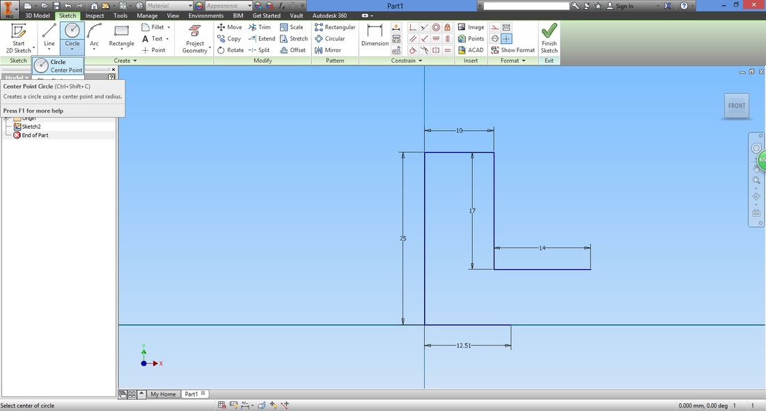
Select the point for the centre of the circle.

Either type in the diameter of 28mm or select the other end of the radius line.
STEP 6Select the Rectangular function. This function allows you to make duplicates of a desired selection.
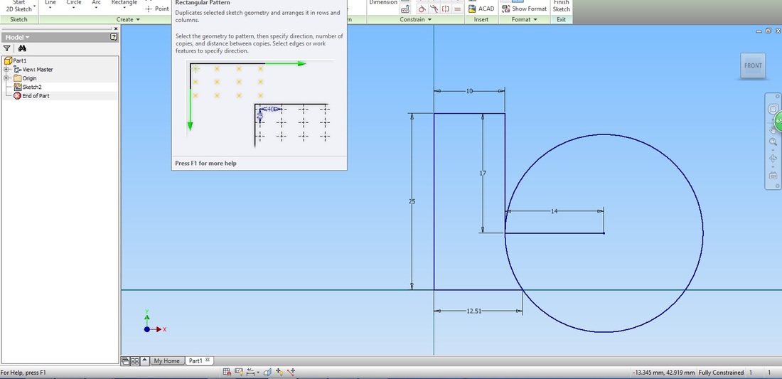
Select the bottom horizontal line (shown in red below) to replicate.
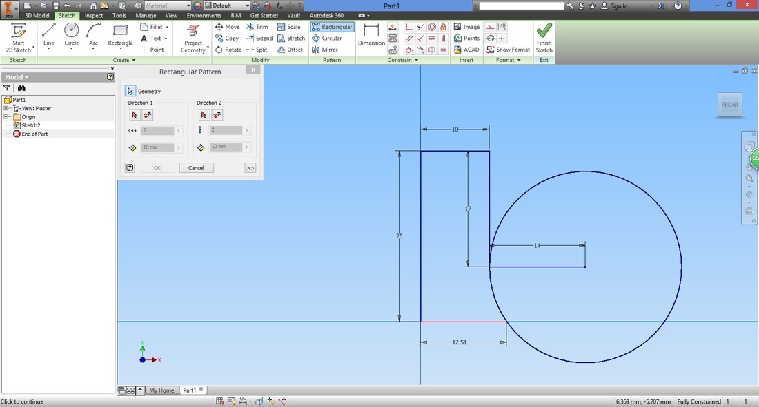
Select Direction 1 in the Rectangular Pattern window.
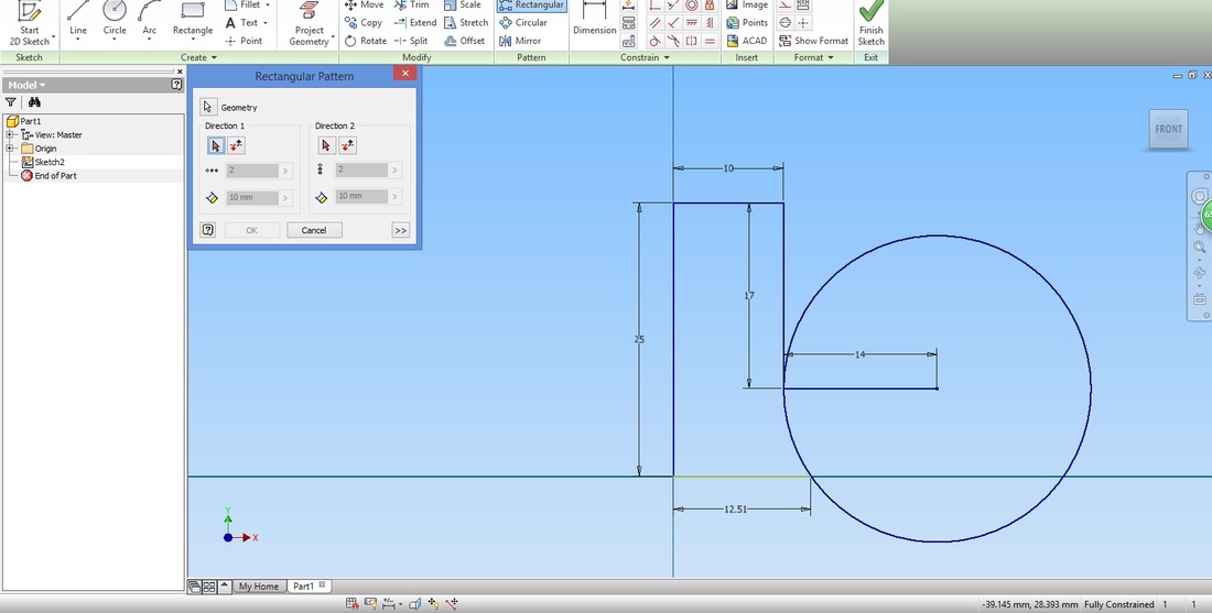
Select the vertical line on the left and the preview will be shown.
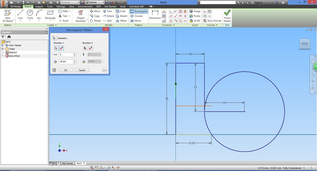
Edit the settings as required in the Rectangular Pattern window and select OK when complete.

Step 7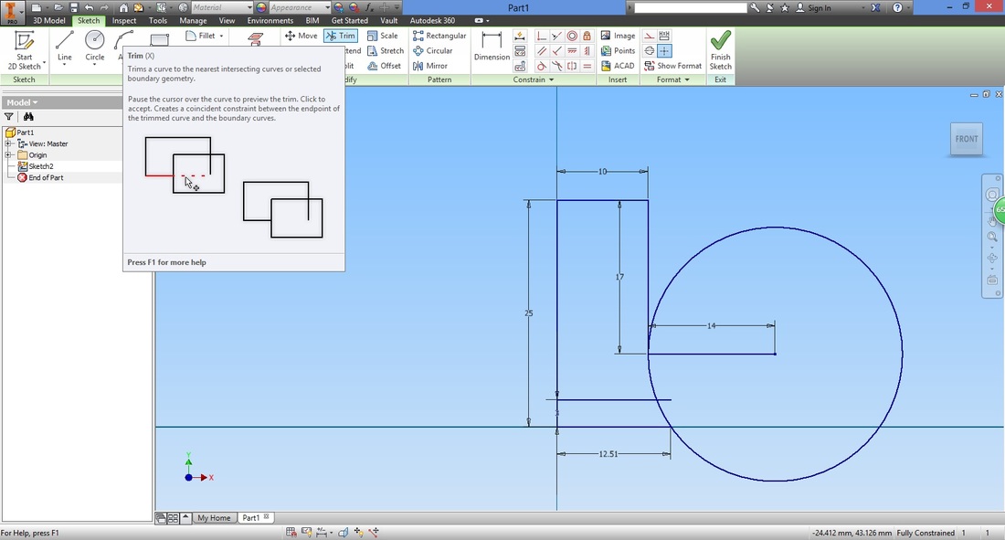
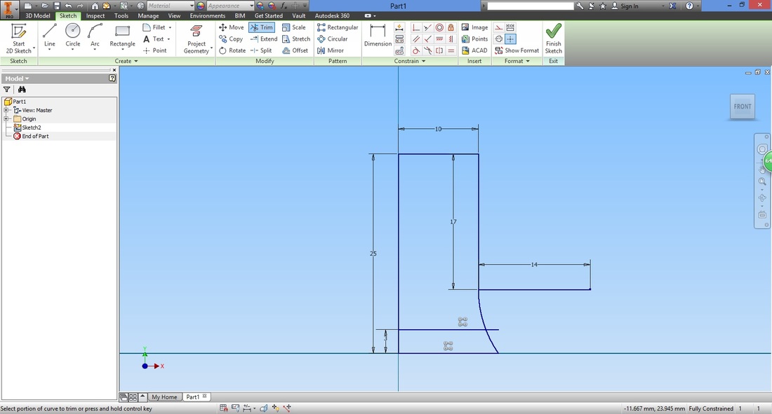
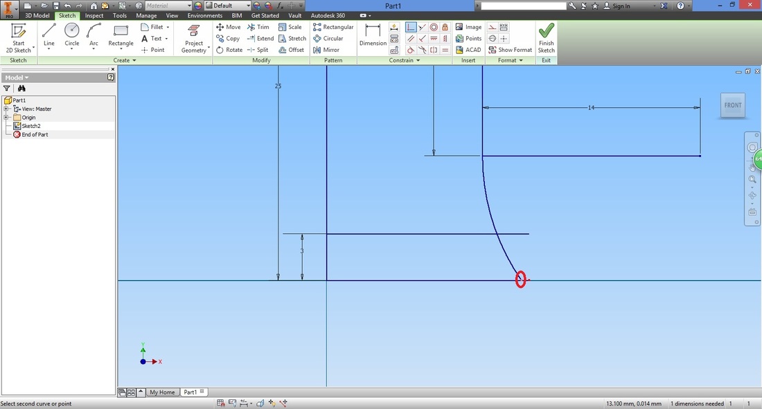
Select the Trim function. This function allows you to trim off lines to its next coincident point (to where it connects to another line or point).
Hover over the circle and observe the preview. The dotted line shows what will be removed/trimmed.
To rectify this, exit the Trim function.
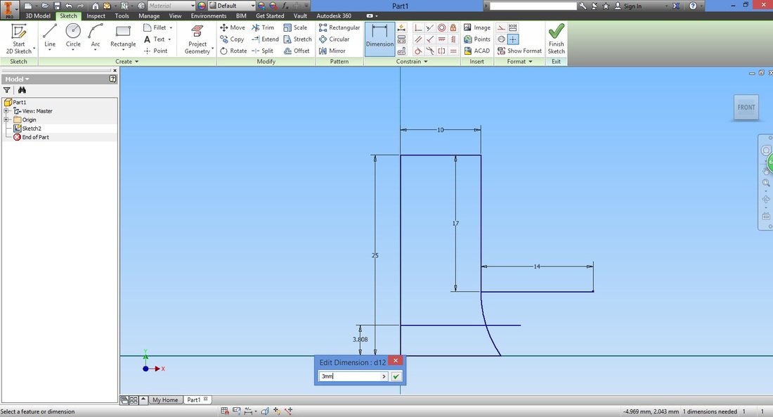
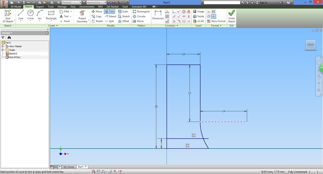
Double click the dimension of the bottom line and change it to extend into the circle. Now open up the Trim function again and hover over the circle. This time the circle trims as we require.
Left click the dotted line for the trim to take effect. Note that the circle is trimmed too much as the bottom line does not coincide with the circle. 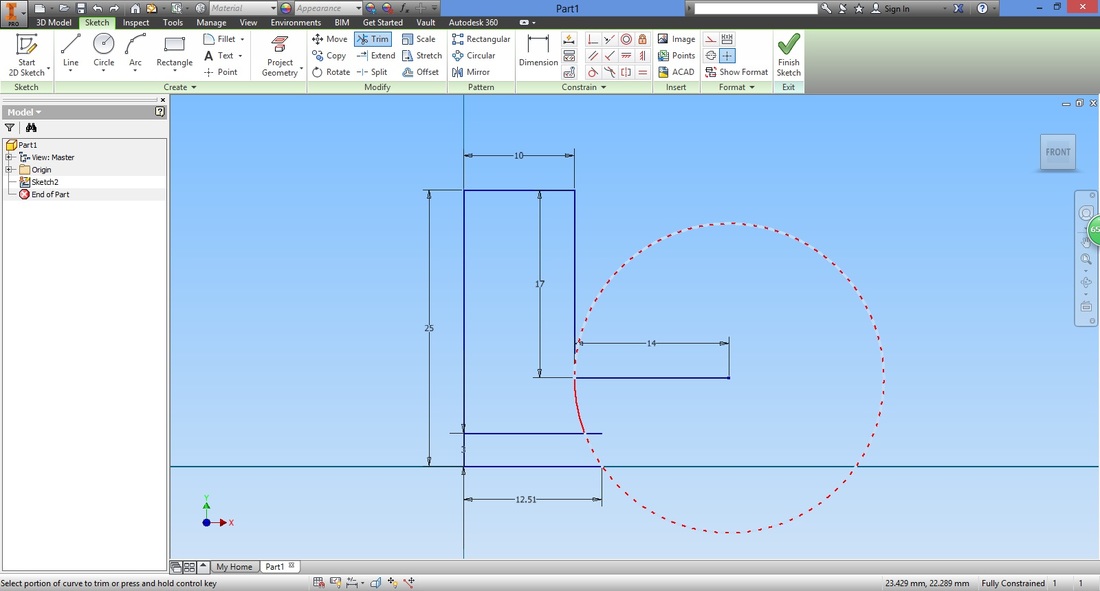
To resolve this, first exit the Trim function.
Double click the dimension of the base line and change it to extend into the circle. 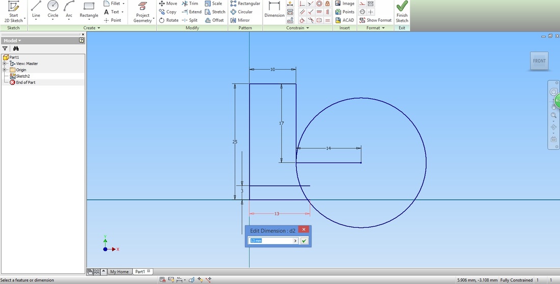
Select the Trim function again.
This time the circle will trim as we desired. Left click the dotted line. 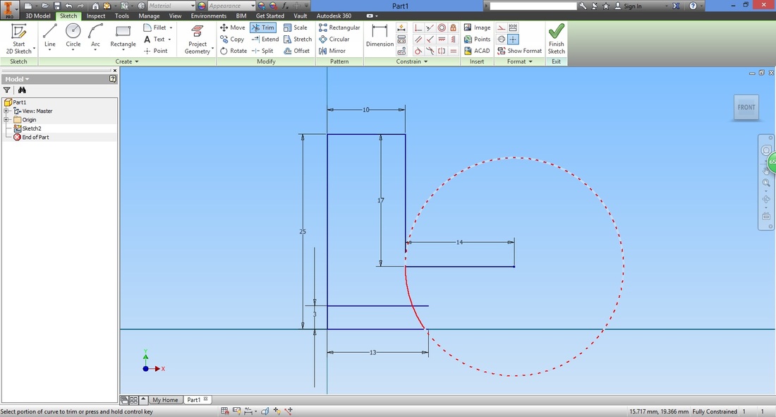
step 8Recall that the base line is still extended and should not be left unattended to.
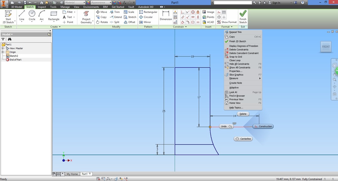
Left click the dimension of the base line and press 'Delete'. When a line is dimensioned, it is given the condition to remain in that length. 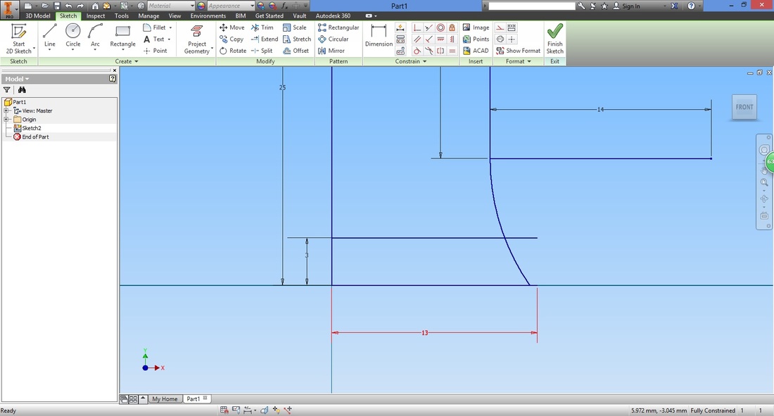
Once the length is deleted, select the Coincident Constraint function. This is a condition that will be applied to the selected lines or points.
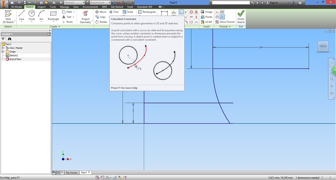
Select the two points shown below to coincide.
The two points will coincide.

step 9Select the Trim function.
If you hover across the extended line (middle line separating the top and bottom region), notice that it does not become dotted.
Because of this, we are unable to shorten the line. Hence we need to delete it.
This is an intentional mistake- remember that when creating lines, it is important to understand the restriction/limitations of constrains and functions. 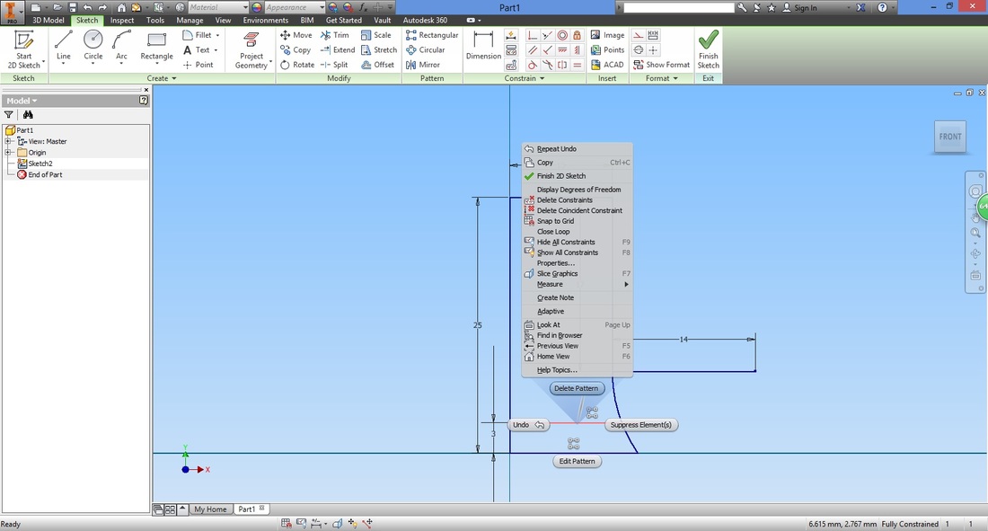
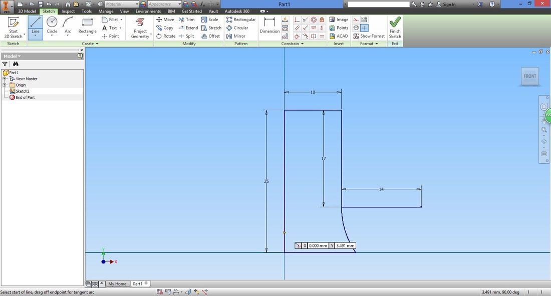
Step 10Select the line function.
Trace along the vertical line on the left and left click for start point.
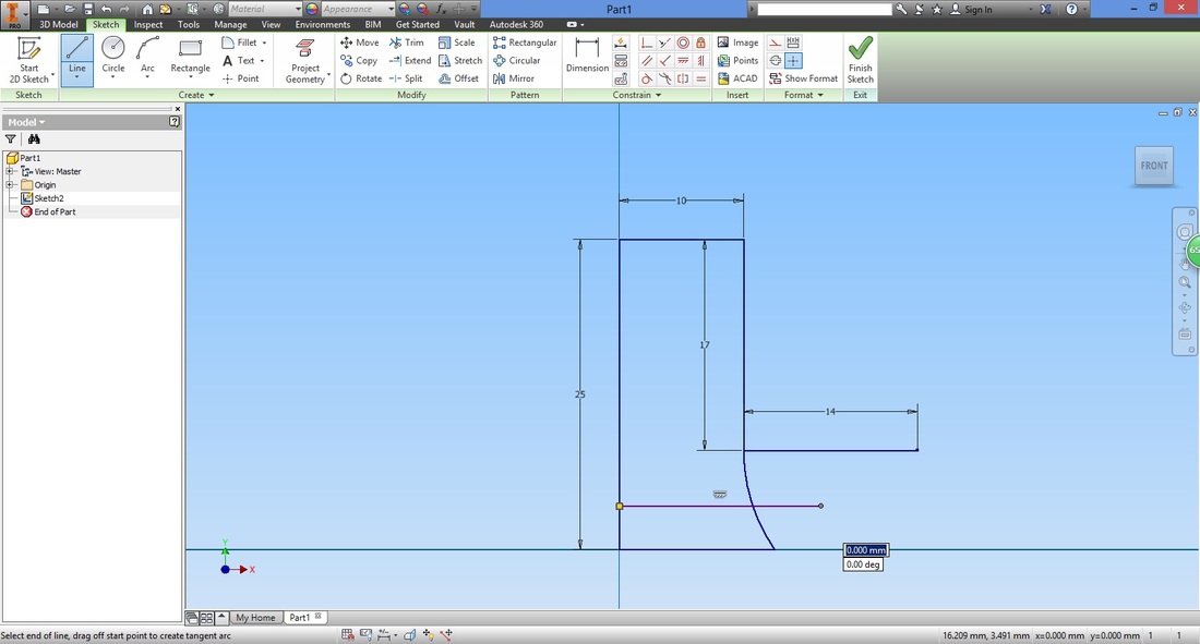
Draw a horizontal line extending to the right. (Do not worry about the distance as we will be trimming it)
Select the Dimension function.

Select the line we just drew and the base line to dimension the distance between them.
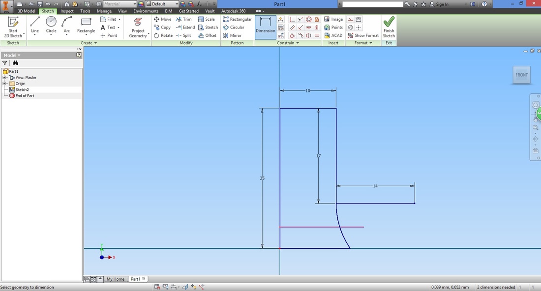
Input the desired base thickness of the L-bracket.
Select the Trim function.
This time the line between the regions can be trimmed. 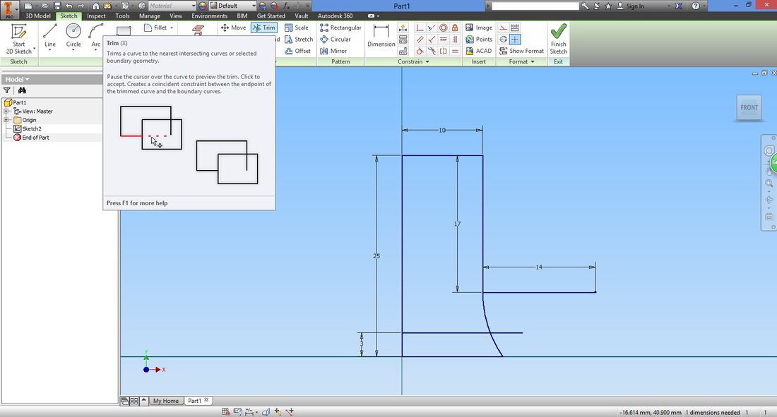
Left click the dotted line to trim.

Right click the line for the radius and change it to a construction line.
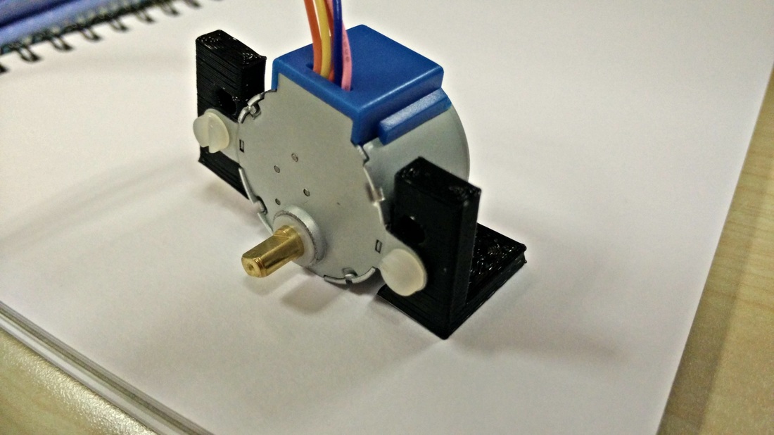
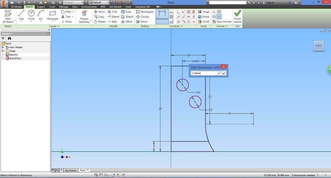
Step 11Here we draw the holes to mount the BYJ48 Stepper Motor. This should tally with that of the motor. Note that there are two types of mounting for the BJY48 motor.
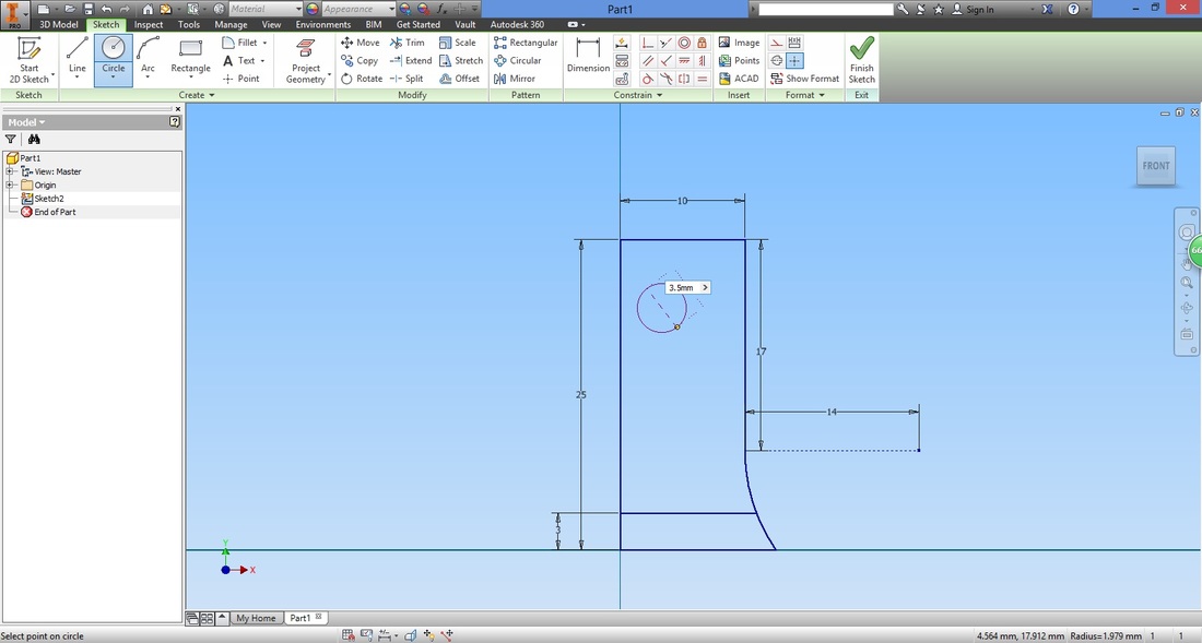
Select the Circle function.
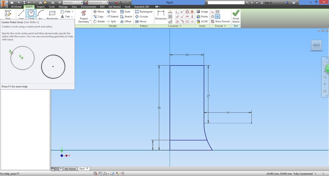
Select any point within the region (we will adjust it using the Dimension function later).
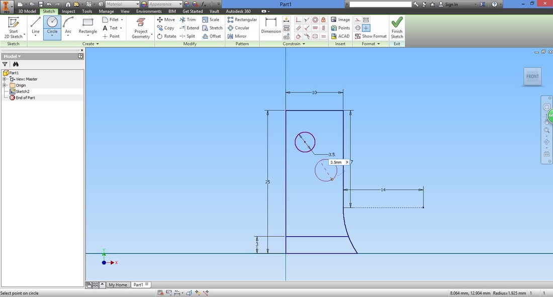
Repeat and draw another circle below.
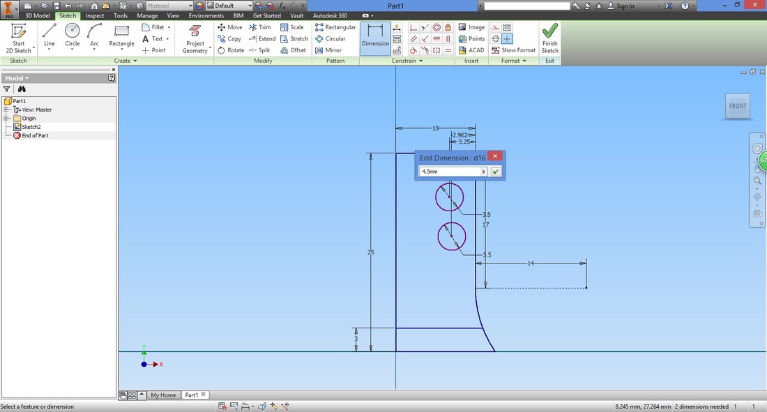
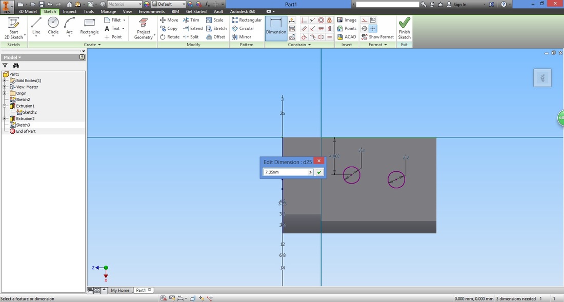
Select the Dimension function.
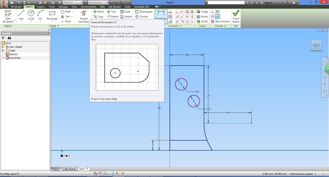
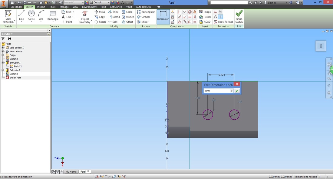
Select the centre of the top circle and the vertical line on the right to provide the distance between them.
Repeat for the bottom circle.
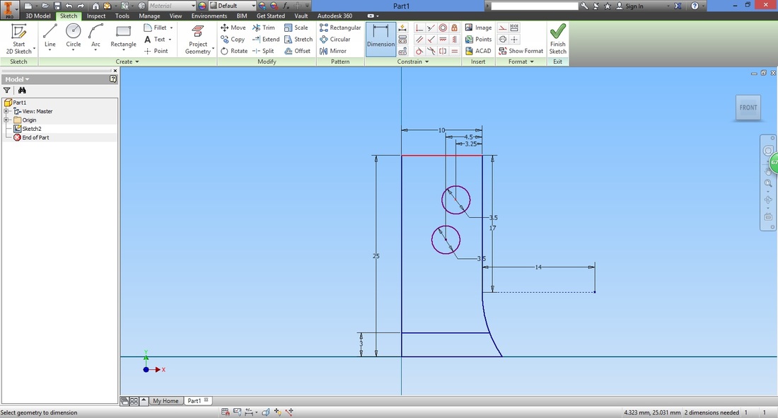
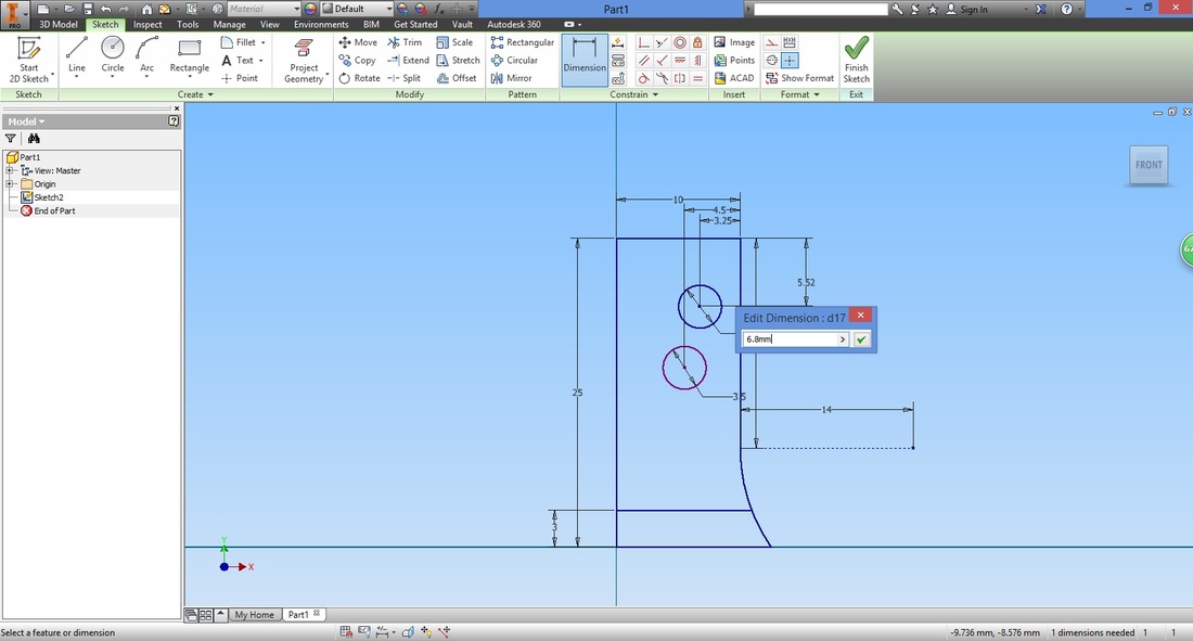
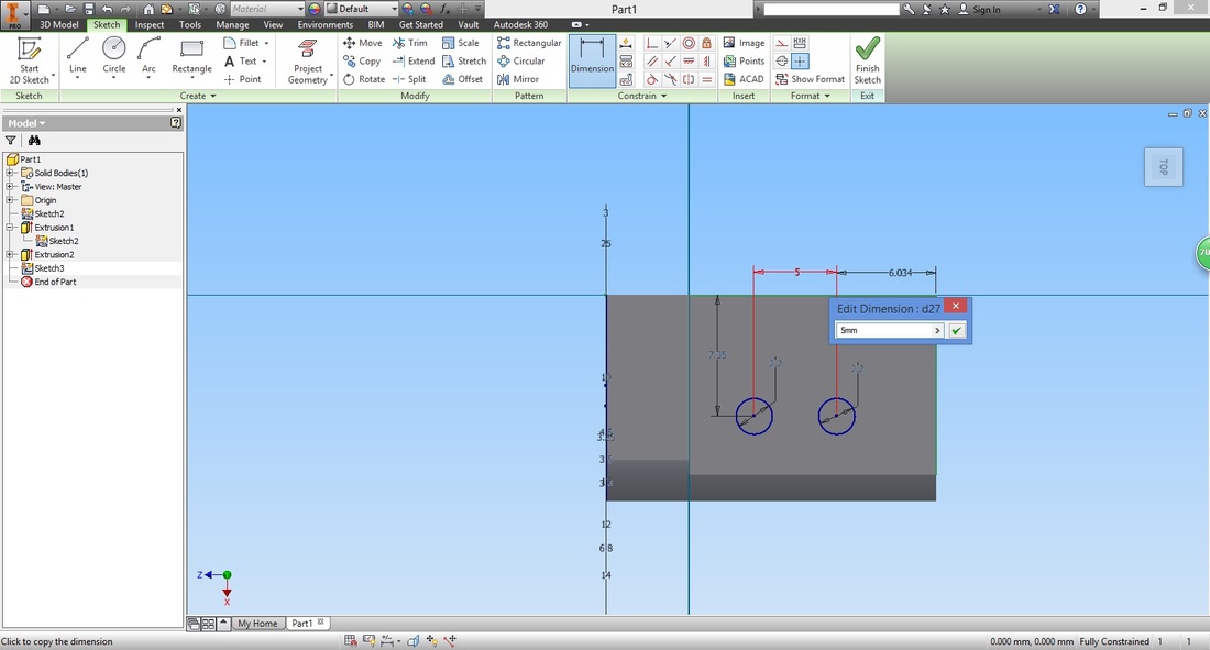
Now repeat but select the top line.
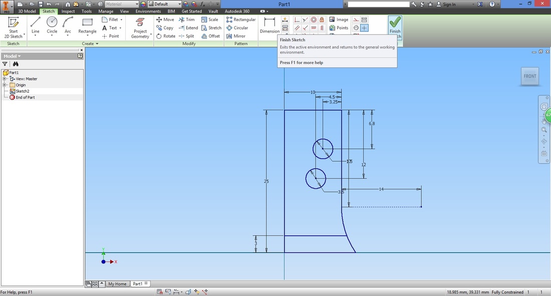
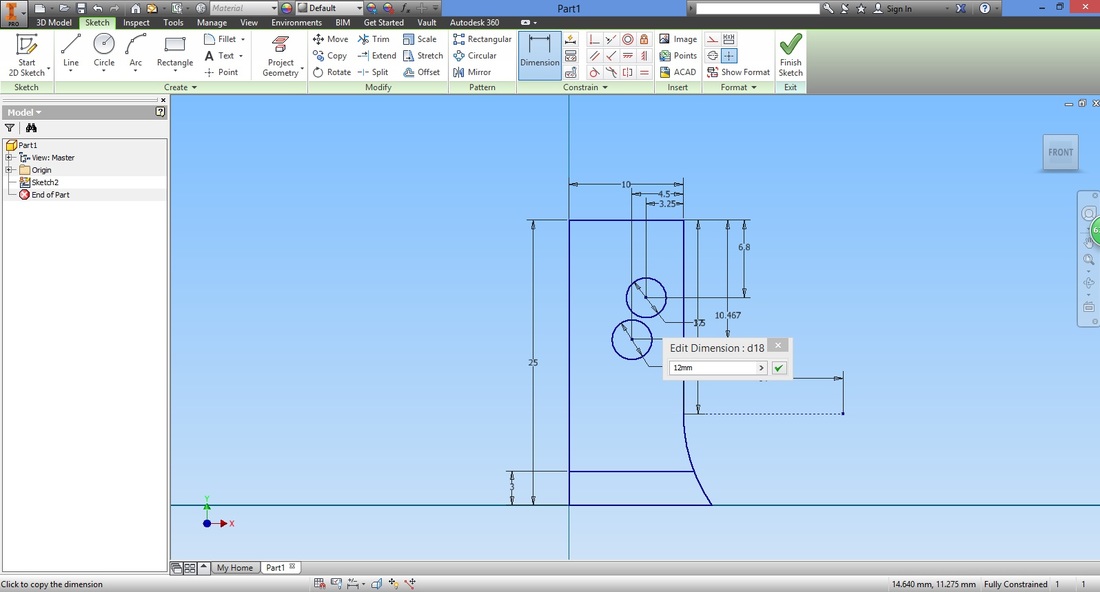
You will have something like this.

Once completed, select Finish Sketch.
The view will automatically rotate.
To rotate the view, Hold Shift key and mouse scroll button. 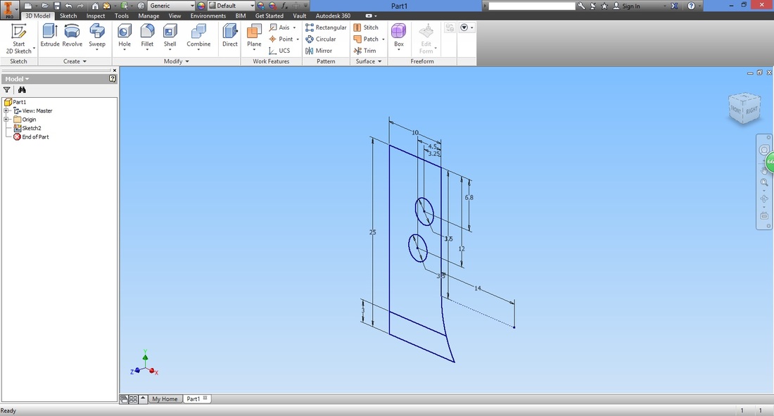
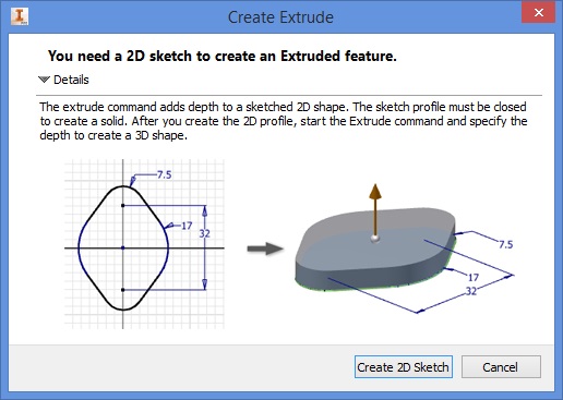
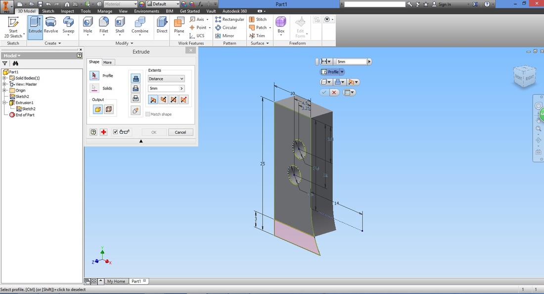
STEP 12Select the Extrude function.
Highlight the region you wish to extrude, by hovering over the region and left-clicking the highlighted area.
Note that if there is gap between the lines (open loop rather than a closed one), the region will not be able to be selected. 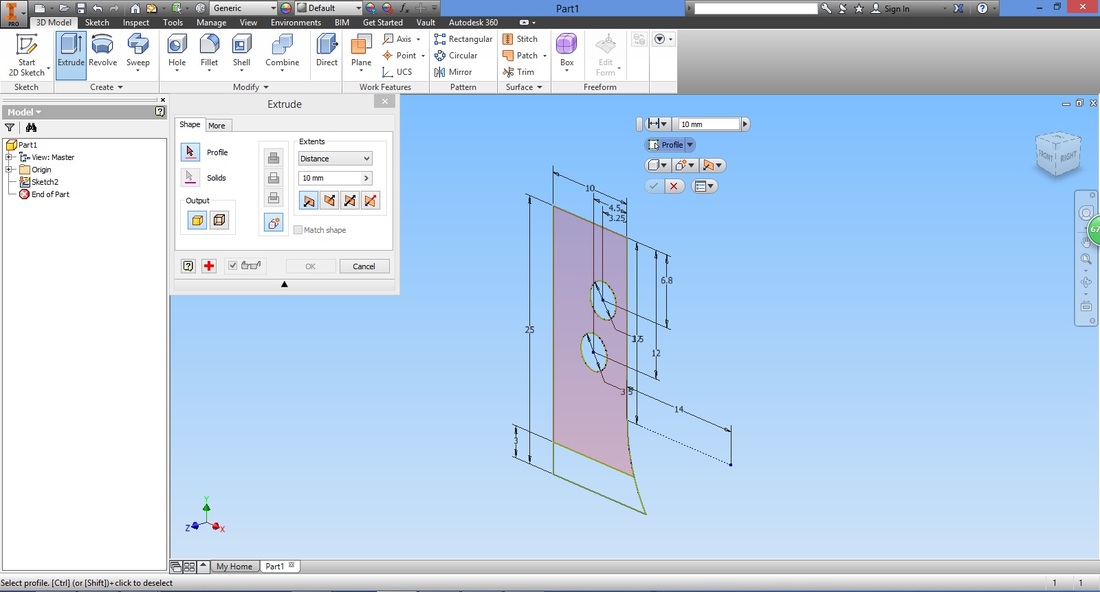
Edit the settings accordingly.
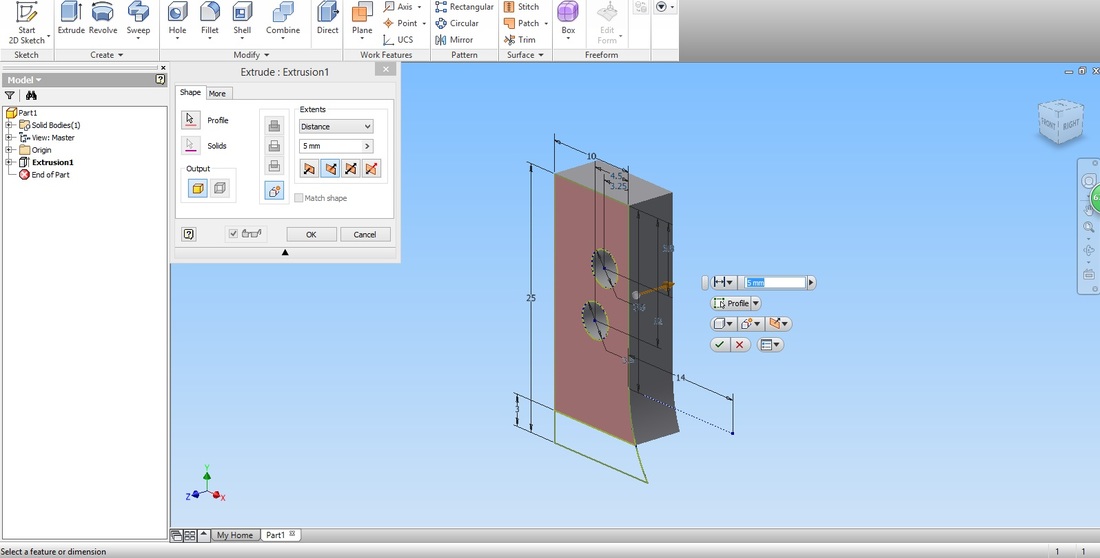
The part will be shown as follows.
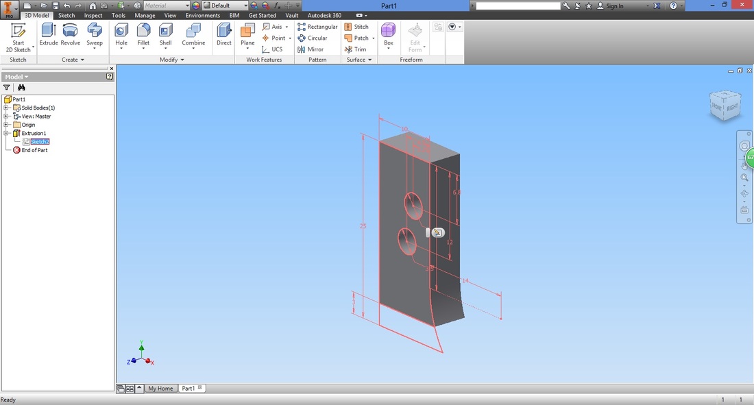
To use the same sketch we used earlier. Right click the sketch name shown in the Model Panel (on the left).
Select Share Sketch. 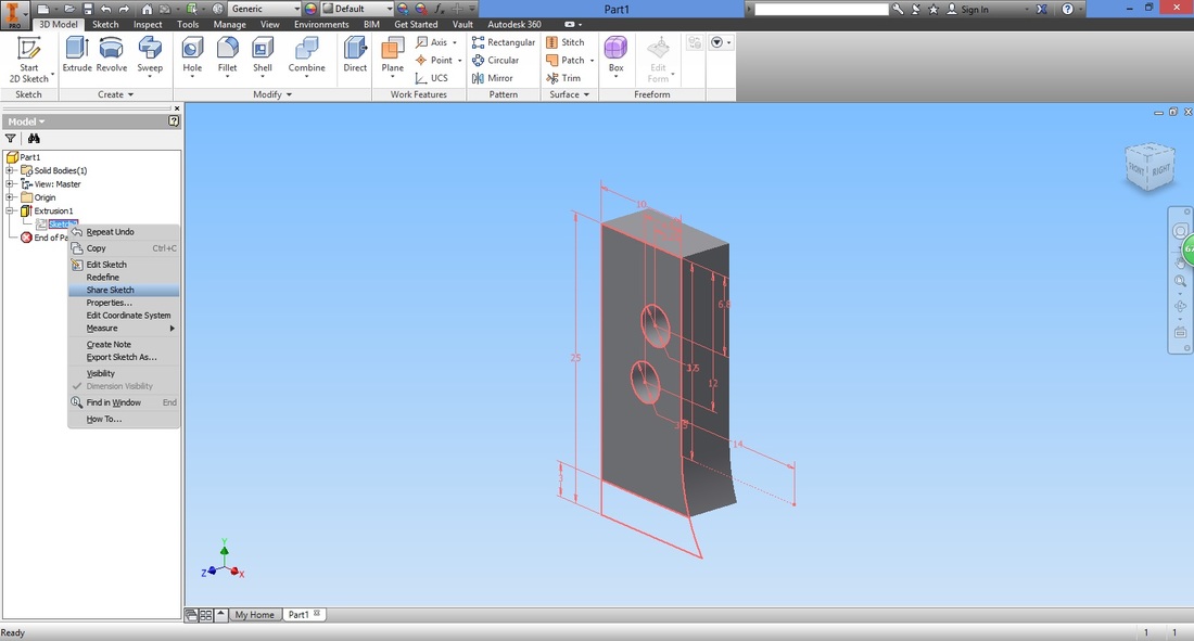
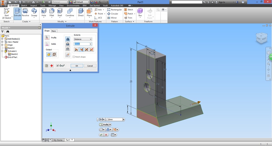
Select the Extrude function again. This time you are allowed to select the Sketch you created.
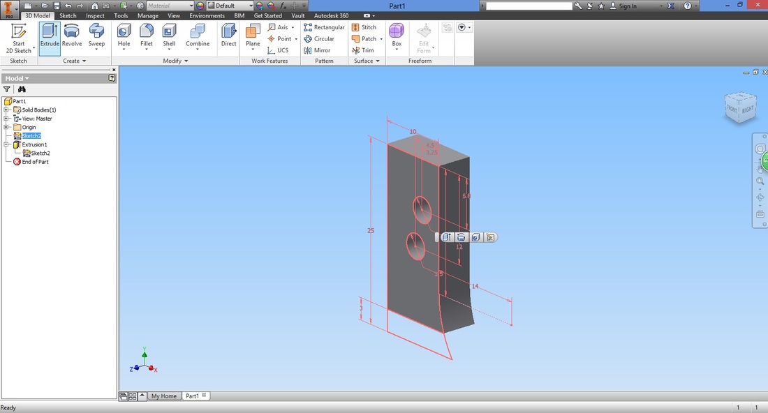
Select the region and settings similar to the first extrusion.
step 13Rotate the view by holding the "Shift" key and mouse scroll.
If the component goes out of view, click the viewing cube at the top right corner. 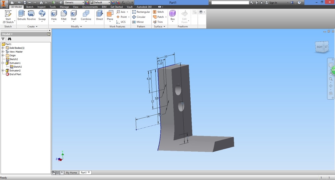
Select Create Sketch function.
Select the face where we intend to sketch. Here we intend to draw two holes that will secure the L-Bracket to the Base Plate.
The dimension of the holes should tally with that of the base plate. (Depending on which component was created first) 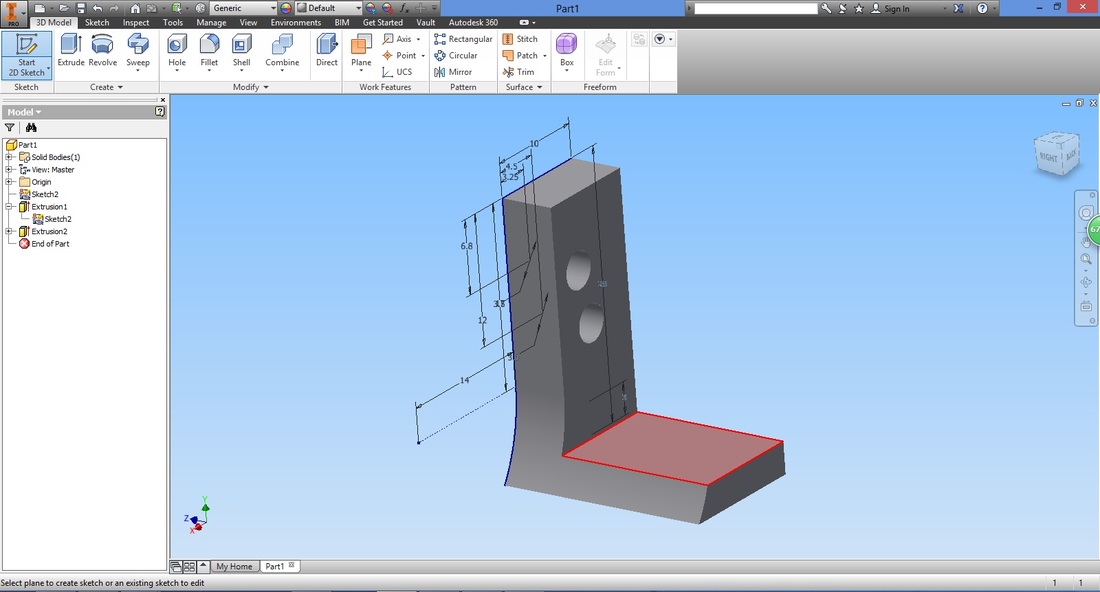
The view will be rotated as shown.

step 14Select Circle function.
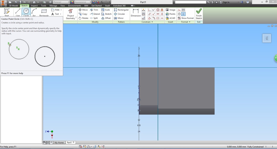
Select any point on the lower region of the L-bracket.
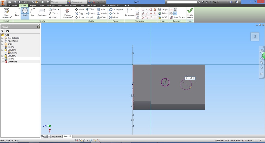
Key in the desired diameter. 
Repeat for another circle.
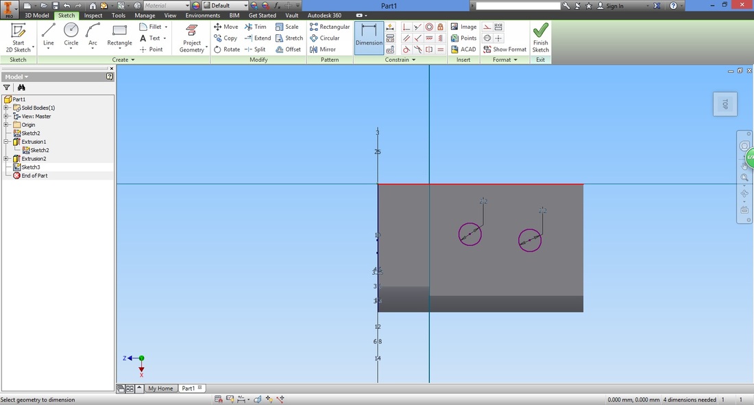
step 15Select the Dimension function to align the holes accordingly.

Select the centre of the circle on the right, then the top line before keying in the dimension.
To align the centre of the holes horizontally, select the Vertical Constraint condition.
Note that if you traced the centre of the first circle to create the second circle, this would have not been necessary. As mentioned before, there are many ways to create the same sketch. 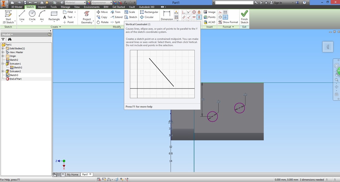
Select the centre of both circles.
Both circles will be aligned as follows.

Select the Dimension function again to determine the distance between the circles.

Select
Repeat
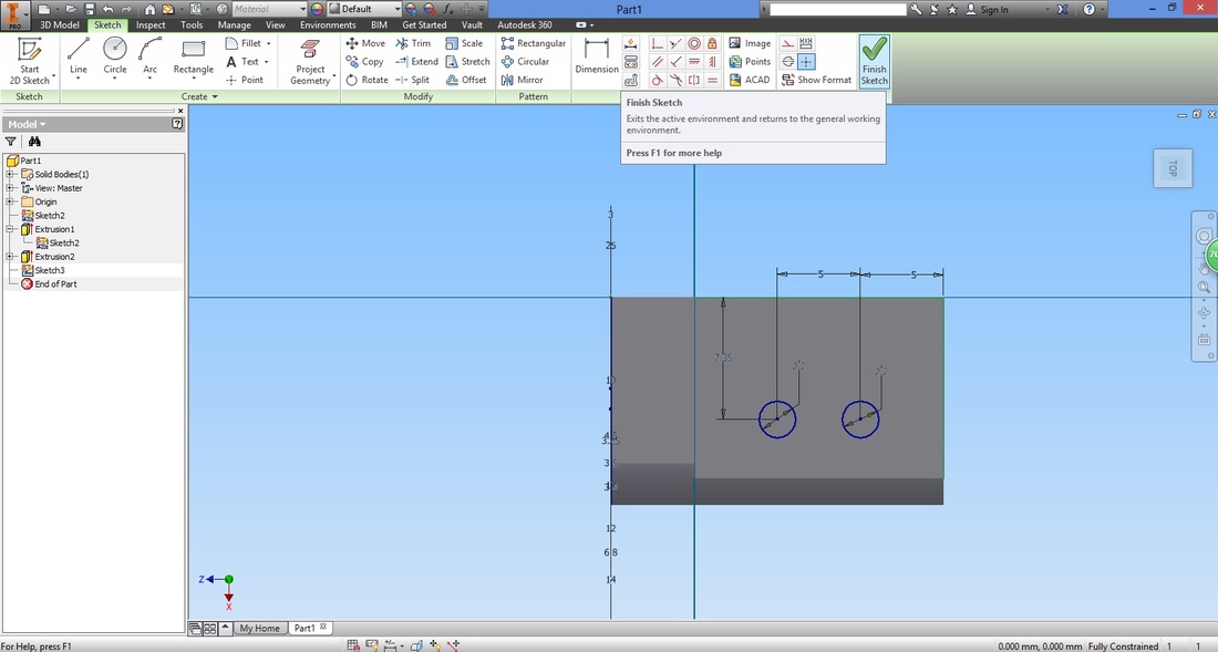
You will have something like this.

Once complete, select Exit Sketch.
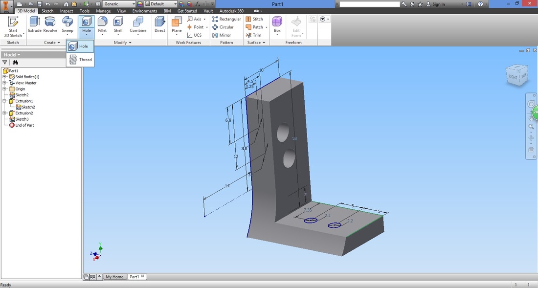
step 16You will return to the 3D part.

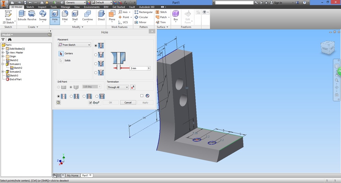
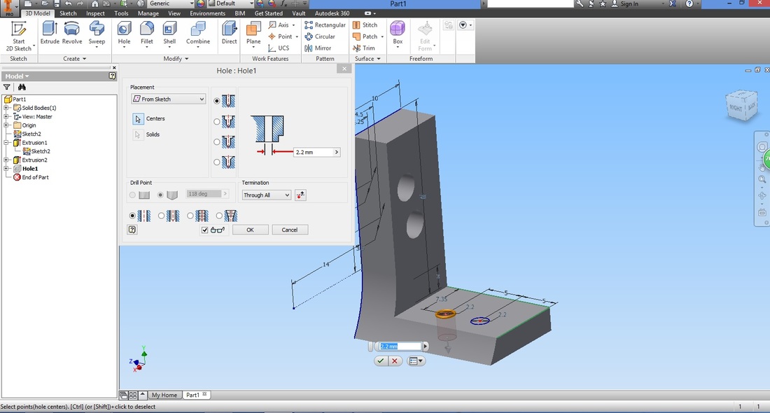
Select the Hole function.
Ensure Centres in the Hole window is selected.
Select the centres of both holes.
Configure the settings accordingly. Note that the diameter of the hole needs to be adjusted to that of the hole drawn.
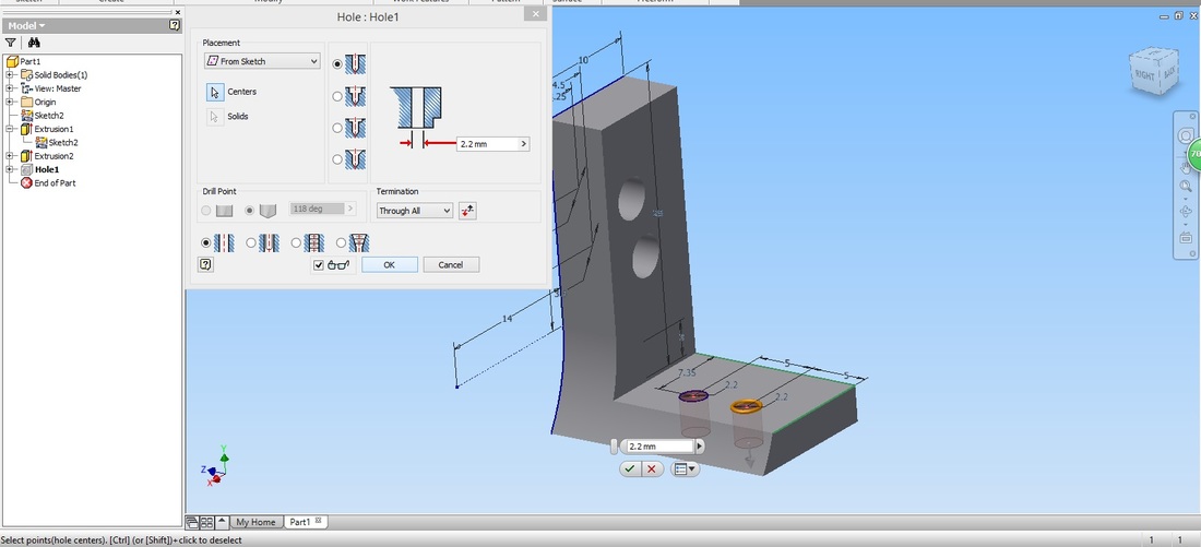
Select OK to complete feature.
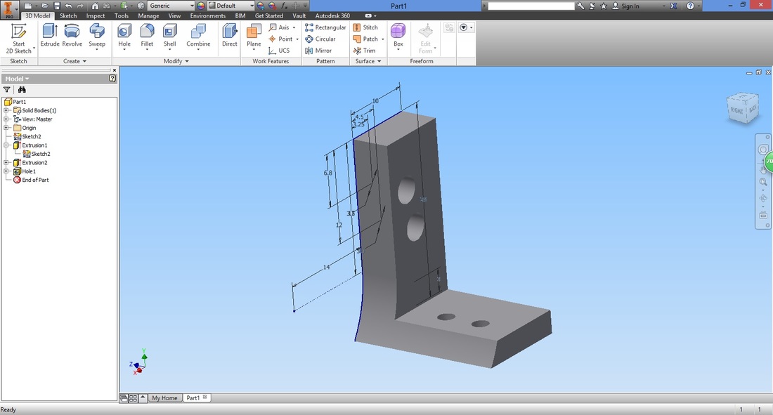
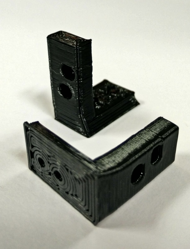
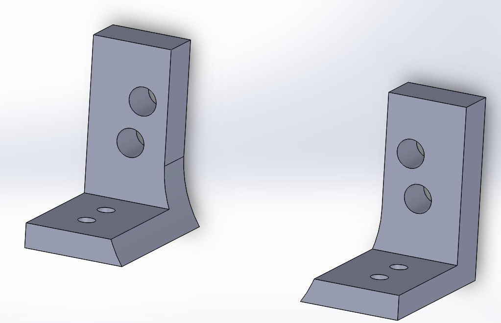
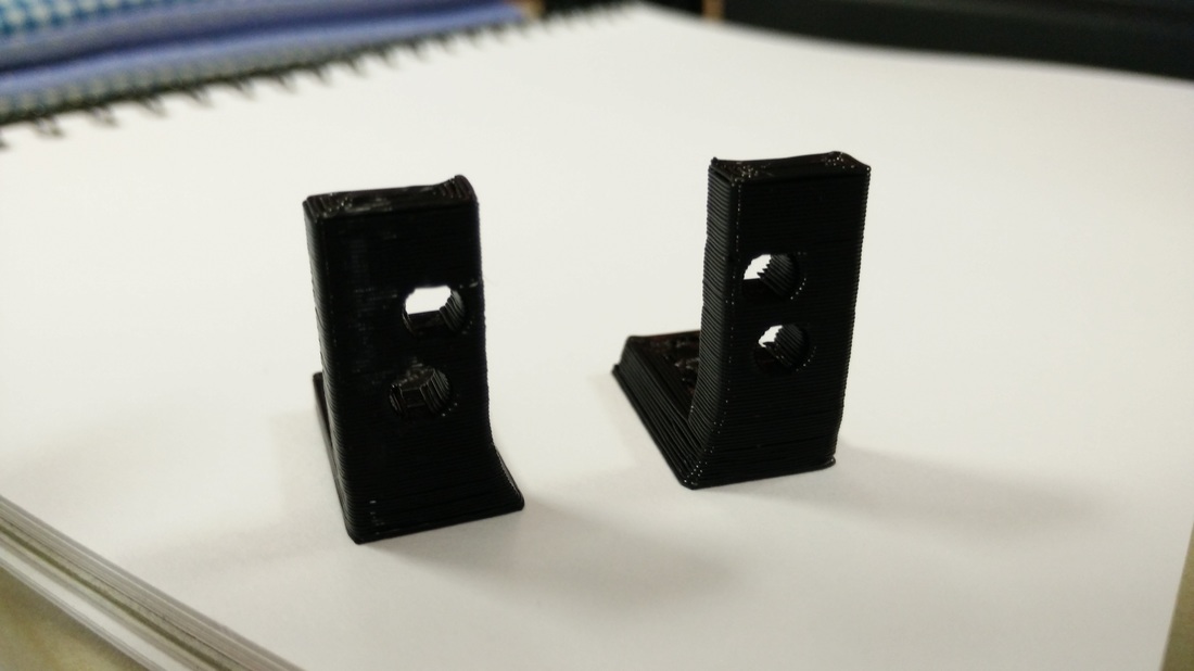
Step 17Congratulations! You have now completed the Left L-Bracket to secure the motor.
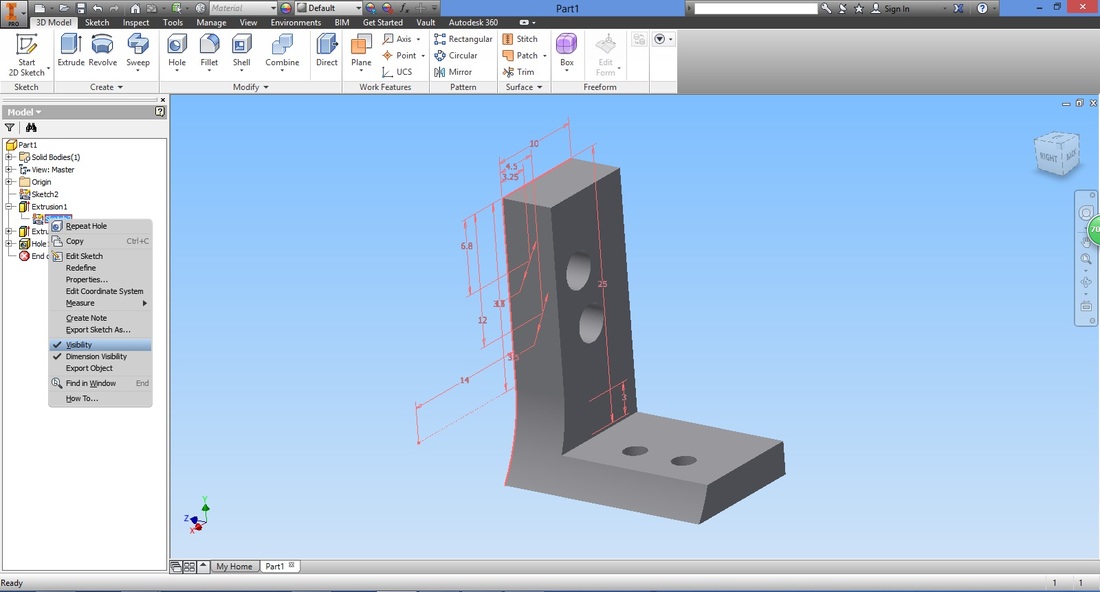
We now proceed to create the Right L-Bracket. First, we hide the dimensions by right clicking the Sketch and un-checking Visibility. (This is just to tidy up the workspace)
Next, select the Offset from Plane function.
Since the Left and right L-Brackets are identical and mirror each other, we intend to use the mirror function. 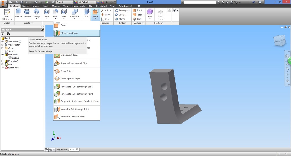
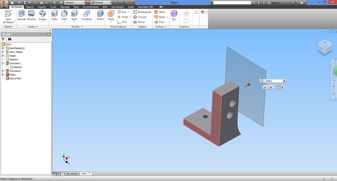
Select the flat surface to offset.
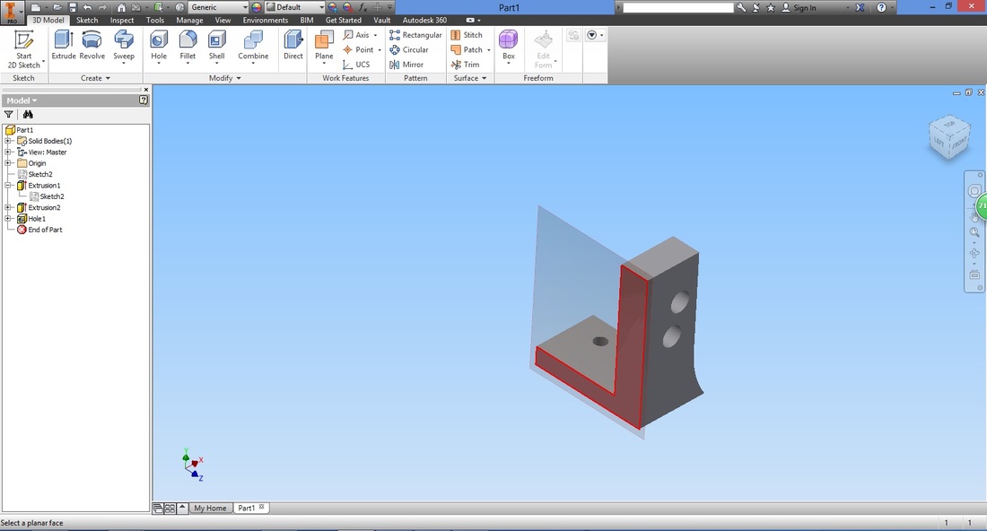
You can drag and pull the plane accordingly.
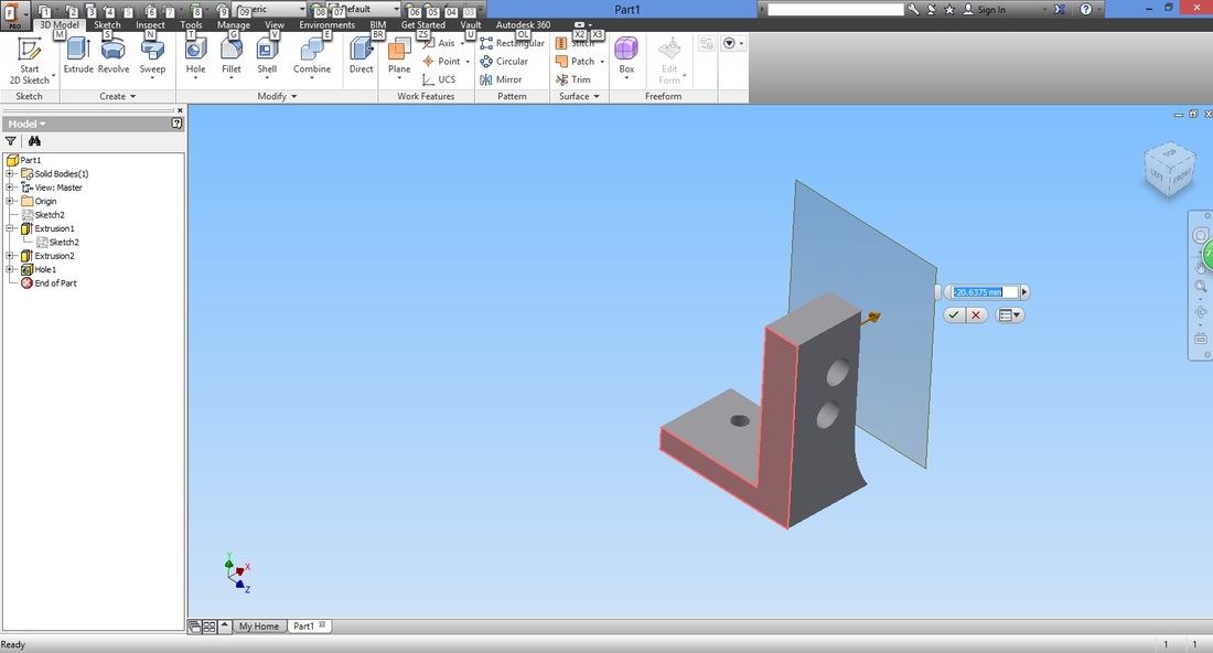
The distance 24mm comes from 10mm (L-bracket thickness) and 14mm (radius of motor).
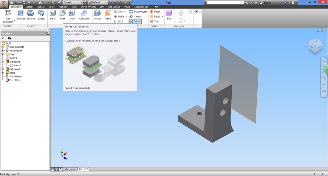
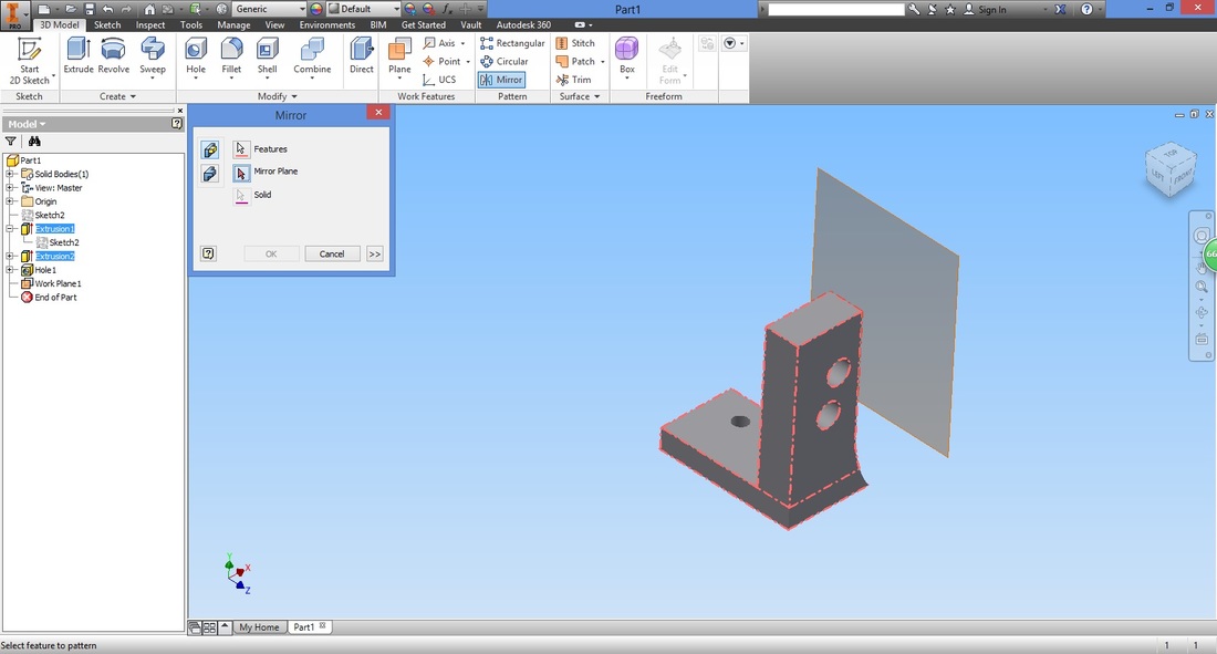
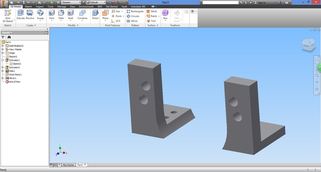
STOP TO CONSIDER: Select the Mirror function.
Ensure Features is selected in the Mirror window.
Select both extrude features by either selecting the component in the workspace or the Model plane. 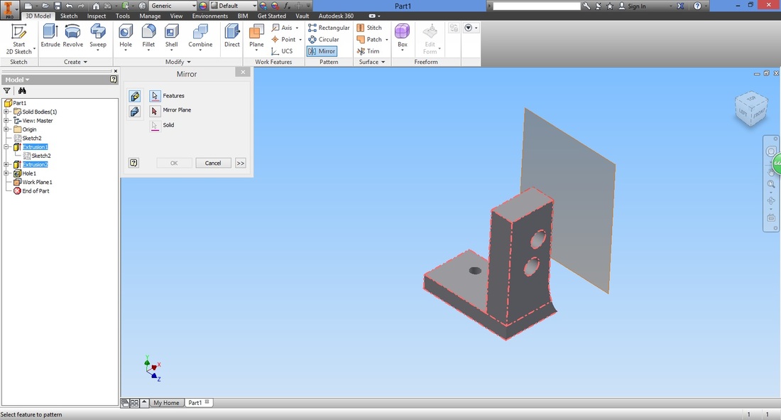
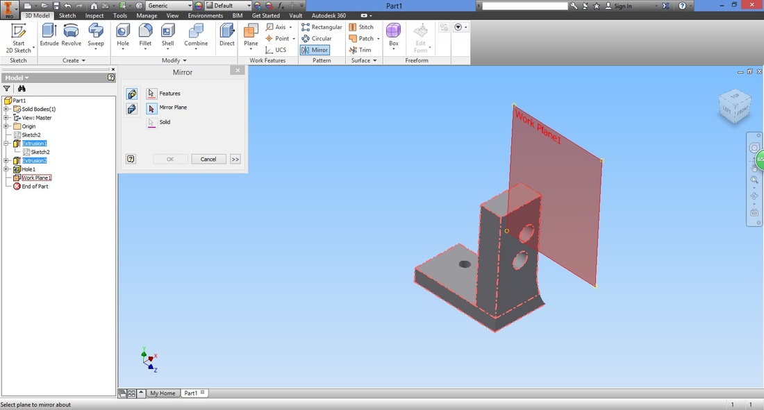
Select Mirror Plane in Mirror window.
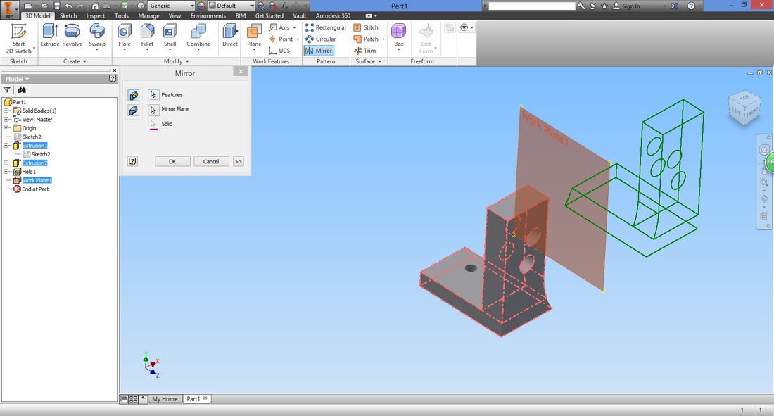
Select the plane created as the mirror plane.
A preview will be shown, if satisfied, select OK.
Right click and hide the visibility of the work plane (mirror plane) created.
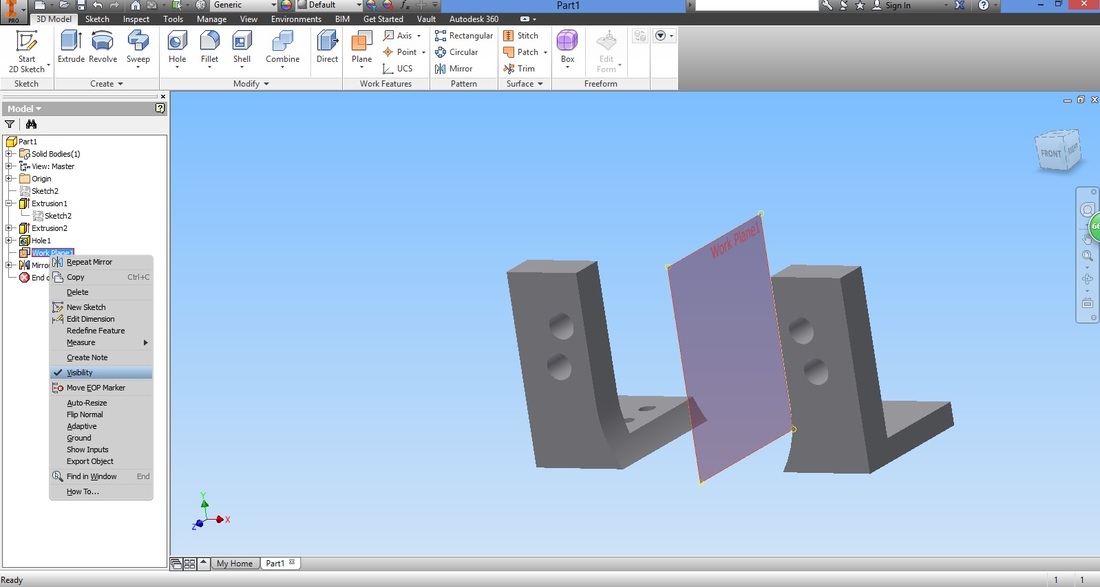
CONGRATULATIONS!
| ||||||||||||||||||||


Download L-Bracket file |
| ||
