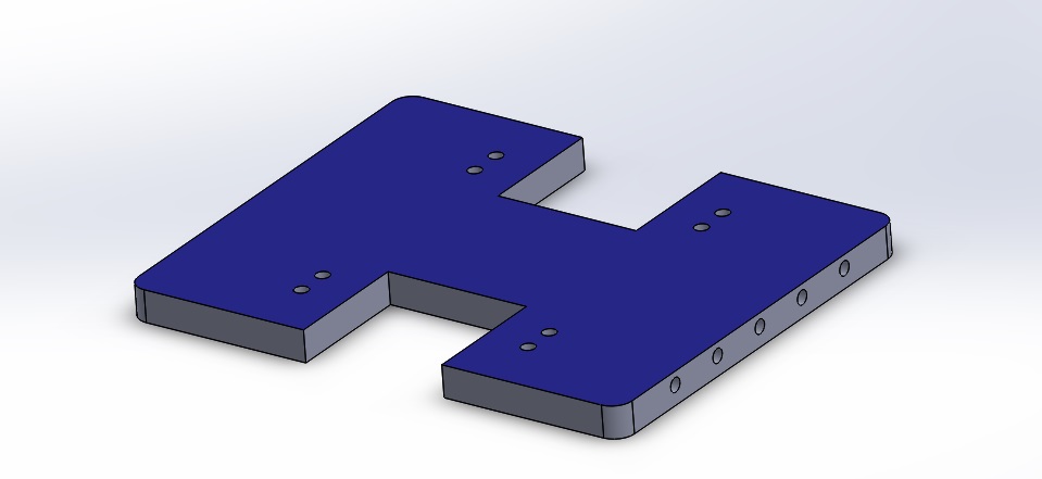
BASE PLATE
|
In the tutorial teaching you step by step how to create an I-shaped base plate, you may have wondered why certain dimensions were used. Let's recap the components used:
|
Let's START!
1. BYJ48 Stepper Motor
step 1 of 2: Find the Dimensions of Part
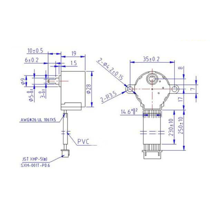
Image taken from:
http://www.sgbotic.com/index.php?dispatch=products.view&product_id=1924
|
L-Bracket (Top View) - slanted surface on left
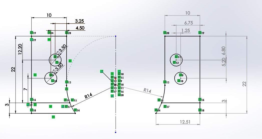
Dimensions of both left and right L-Brackets
|
With these dimensions, consider how you would like to the orientate the part. Here we choose to orientate the flat surface upwards as that is where the wires will protrude and be connected to the controller (Arduino).
|
As you would notice, the L bracket will hold the motor in place. Hence, the dimensions we need to consider are
|
|
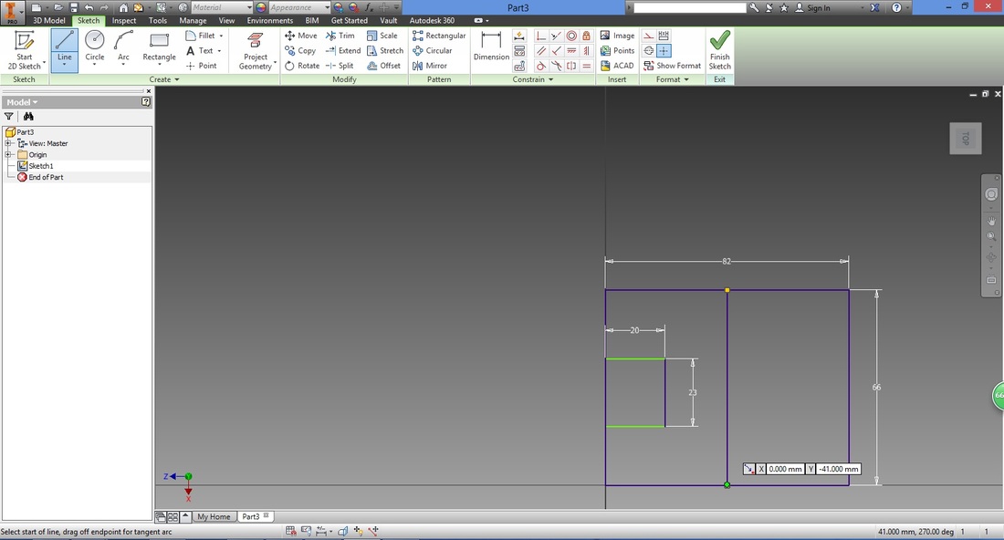
step 2 of 2: designing based on info
Length #1
|
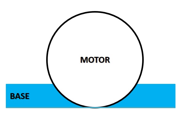
First we look at how high the motor is lifted.
Note that this height will affect the size of your tyre/wheel (which should also take into consideration the height of the castor wheel if one is used). Here we have aligned the base of the motor to the base of the base plate.
|
Side View
|
Next, take a look at the diagram below with the added gap we are designing for, before proceeding to the calculations.
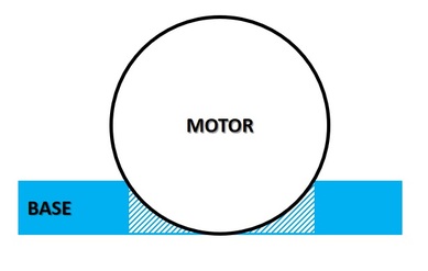
Side view of the gap to be created.
|
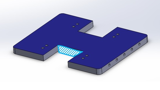
The shaded area seen from the side view is shown here.
|
Now comes the interesting part, applying the mathematics you've learnt in school.
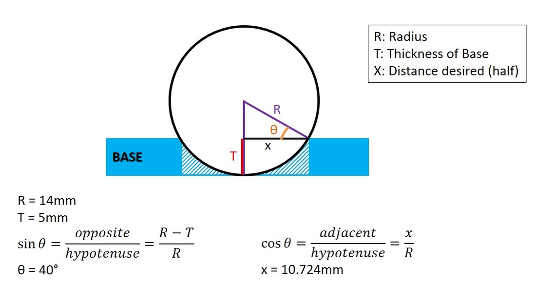
Here we learn that length #1 should be 2X = 21.448mm.
So why did we use 23mm instead?
This is because this is the real world, and tolerances are required. Do change it to suit your needs.
So why did we use 23mm instead?
This is because this is the real world, and tolerances are required. Do change it to suit your needs.
Length #2
Recall the dimensions above, here we look at the "thickness" of the motor.
Length #2 requires to be 19mm. However, we add some tolerance and adjusted it to 20mm.
Length #2 requires to be 19mm. However, we add some tolerance and adjusted it to 20mm.
With both of these lengths, we obtain the following.
hole dimensions
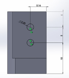
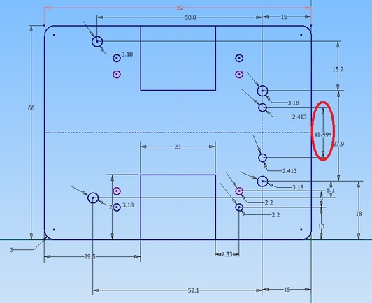
One of the most important things when it comes to assembling components together is to ensure that the holes are aligned (to be screwed or secured). Hence it is important to ensure the holes drawn match those of the other component (L-Bracket).
Observe how the dimensions of the L-Bracket matches those circled in the Base Plate.
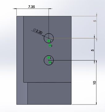
L-Bracket (Top View)
|
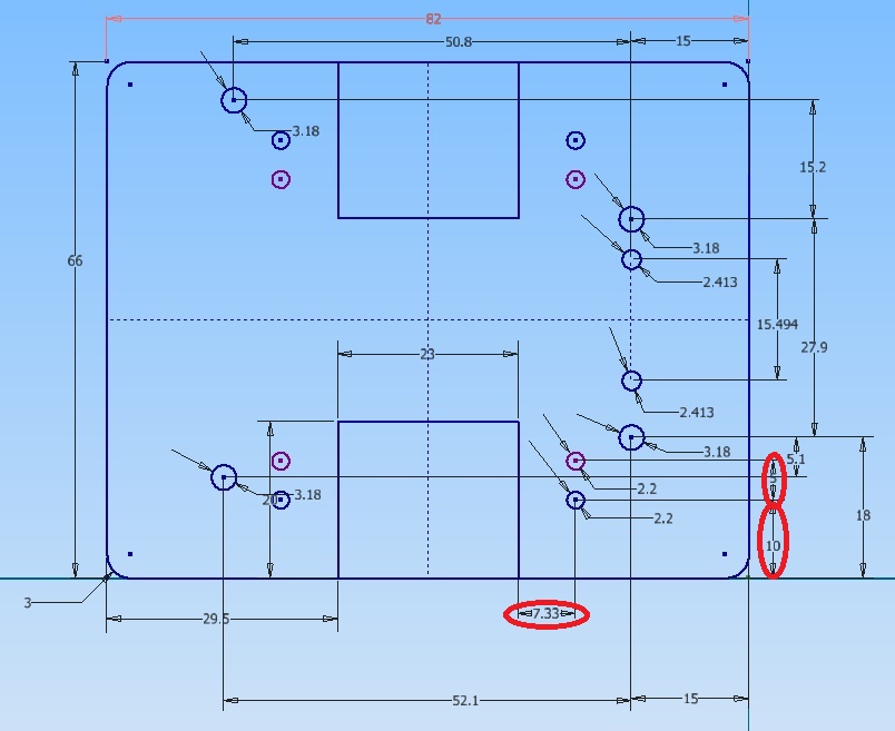
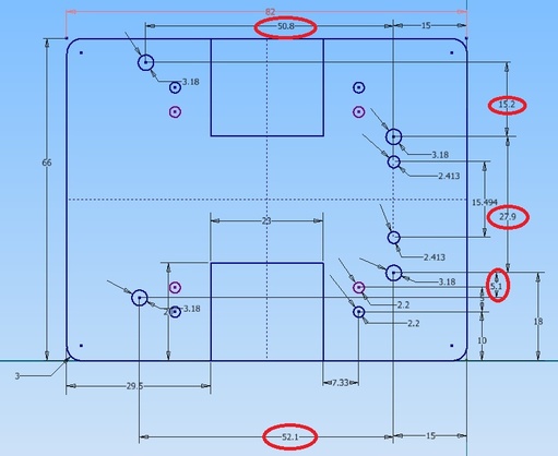
Base Plate dimension (those circled in red tally with that of the L-bracket)
|
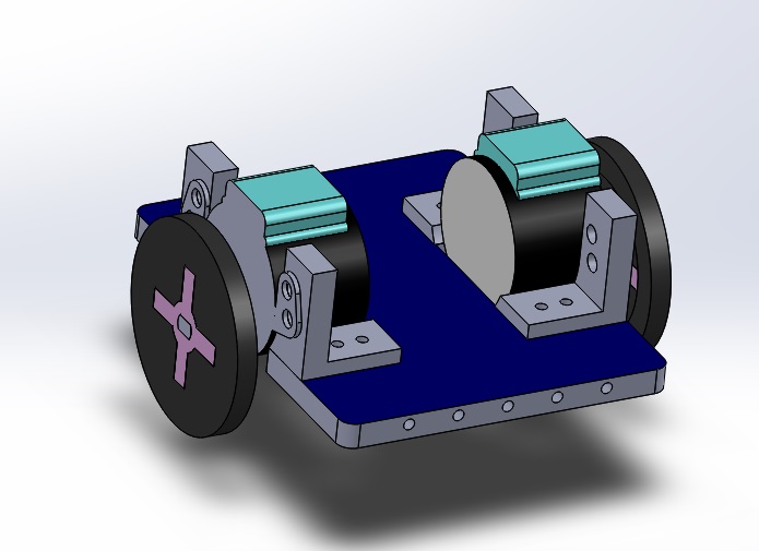
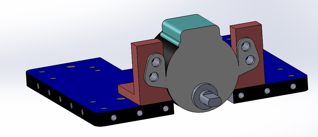
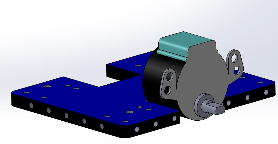
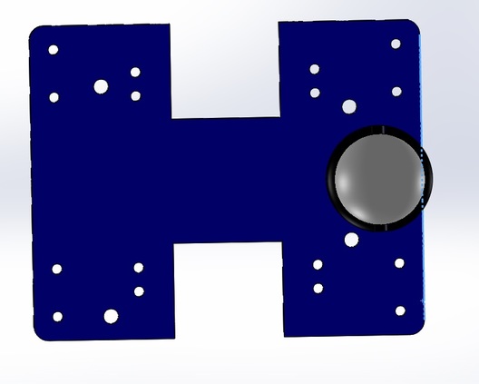
BYJ48 STEPPER MOTOR integrated!
The photo below of the 3D models show the desired placement of the stepper motor (the L-brackets are not shown).
2. Ball Caster with 3/4" Metal Ball
step 1 of 1: Find the dimensions of part
These dimensions are usually provided by the supplier and should be taken into consideration before purchasing the part.
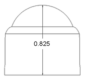
|
|
Image taken from: http://www.sgbotic.com/index.php?dispatch=products.view&product_id=1446
First thing to note is that dimensions are not always in the unit system you desire. Here it is in inches, though we use the metric system in tutorials.
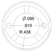
Here we are only interested in the distance of the holes that its diameter.
This is because that is the only information required to mount the caster wheel onto the base plate.
This is because that is the only information required to mount the caster wheel onto the base plate.
The diameter of the holes are 2.413mm and they are 15.494mm apart.
Another dimension that should be taken into consideration is the outer radius of R.438 (11.1252mm). This is because we want to give enough allowance between its outer most radius and the edge of the base plate.
Here we used 15mm.
Here we used 15mm.
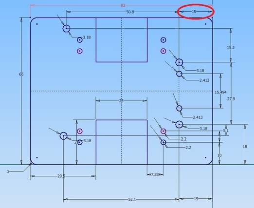
Observe how the caster wheel protrudes out of the edge if not enough allowance is provided as shown in the diagram below.
Pay attention to the symbol and unit used. A good trick is to always check if the values make sense so that you do not follow the values blindly.
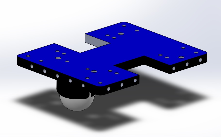
BALL CASTER WITH 3/4" METAL BALL INTEGRATED!

3. Arduino uno
step 1 of 1: Find the dimensions of part
Here we look at the holes that will hold the Arduino UNO board.
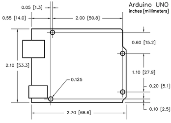
Image taken from:
http://www.fingertechrobotics.com/prodimages/electronics/arduino_uno_dims_lg.png
The diagram below shows how the dimensions are translated into the Base Plate.
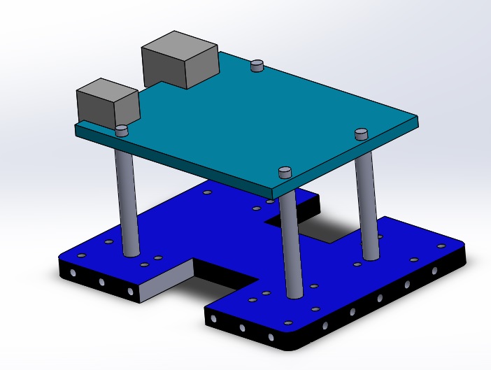
Arduino UNO INTEGRATED!

