
|
The following is a tutorial to teach you step by step how to create an Cover/Shell using the educational version of Autodesk Invertor Professional. If you have yet to install it, you may refer to the link below.
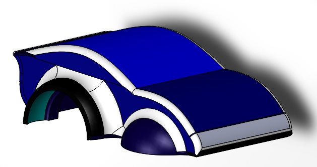
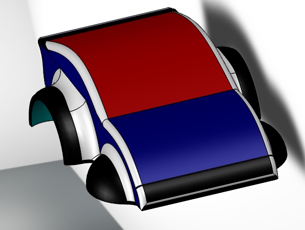
This base plate dimensions were drafted in consideration of the following components:An example of how this Shell is used is shown below.
Here's a few good things to remember before we begin:
As this serves as a tutorial, there are intentional hiccups along the way to give you a better learning experience of what to look out for in the future.
For this tutorial, we assume you have completed the base plate as its measurements are required prior to creating this. LET'S START!STEP 1Launch Autodesk Inventor Professional.
The homepage will appear as shown below. Select PART to create a new part. WHAT IT MEANS: 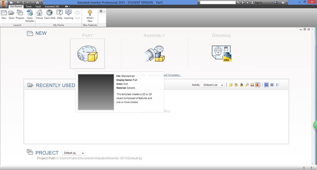
STEP 2 (IMPORTANT)A good habit to have is to check and set the dimensions of your drawings.
Under the Tools ribbon, select Document Settings. 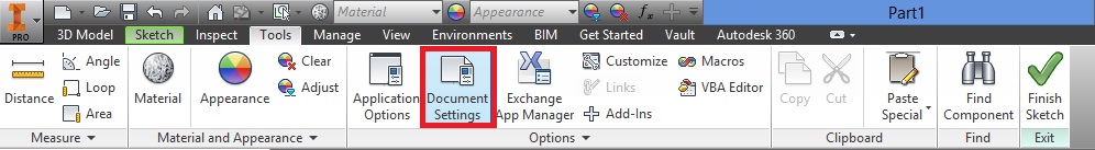
A window will then appear.
Select the Units tab, and adjust accordingly. 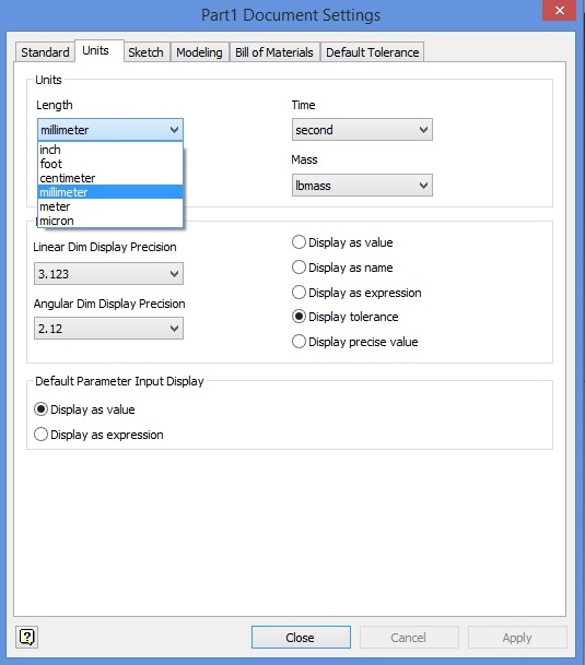
Select Apply then Close, to apply settings.
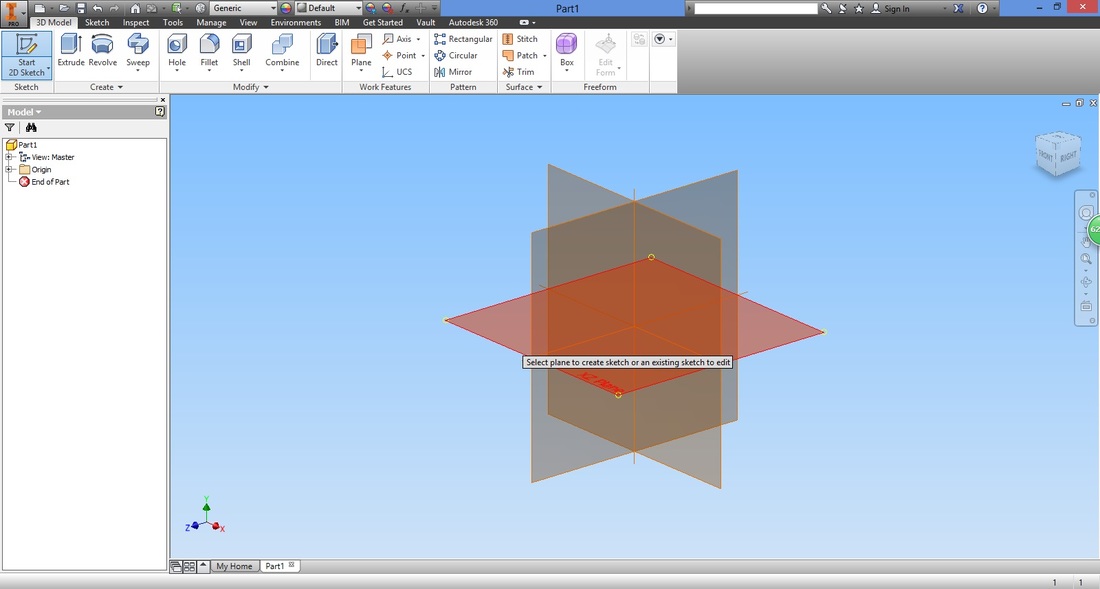
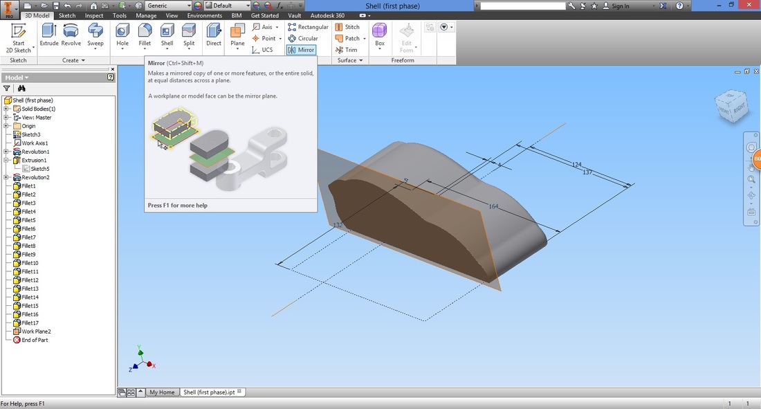
STEP 3In the 3D Model ribbon, select "Start 2D Sketch".
Notice that if you hover over the function for long, a quick introduction of the function will appear. 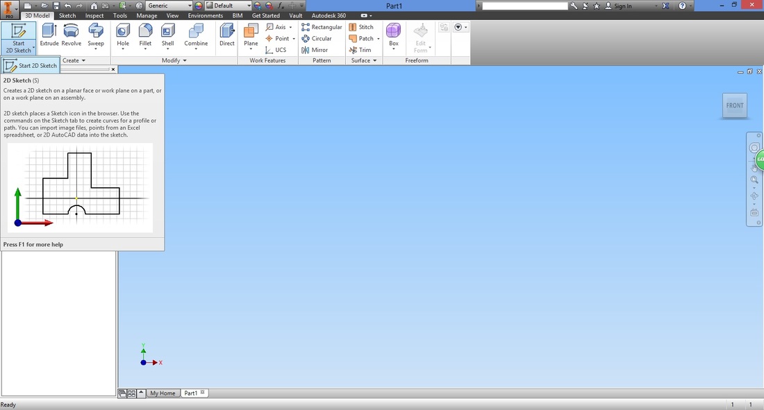
Next, select the plane you would want to draw on. Here I've selected the XZ Plane.
WHAT beginners SHOULD KNOW: STEP 4From the Sketch ribbon, select the Rectangle function.
Hover over the origin. The cursor will turn into a green circle. 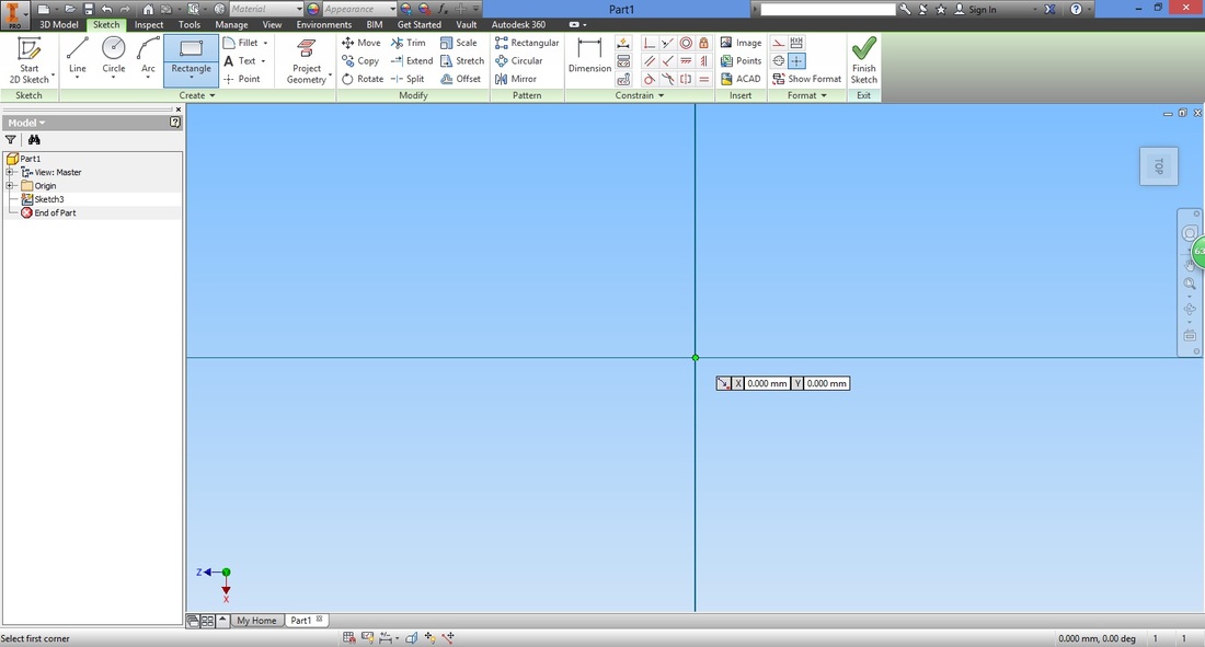
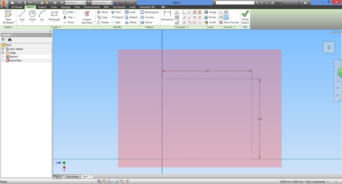
Draw the rectangle with the dimension of four of the base plates combined.
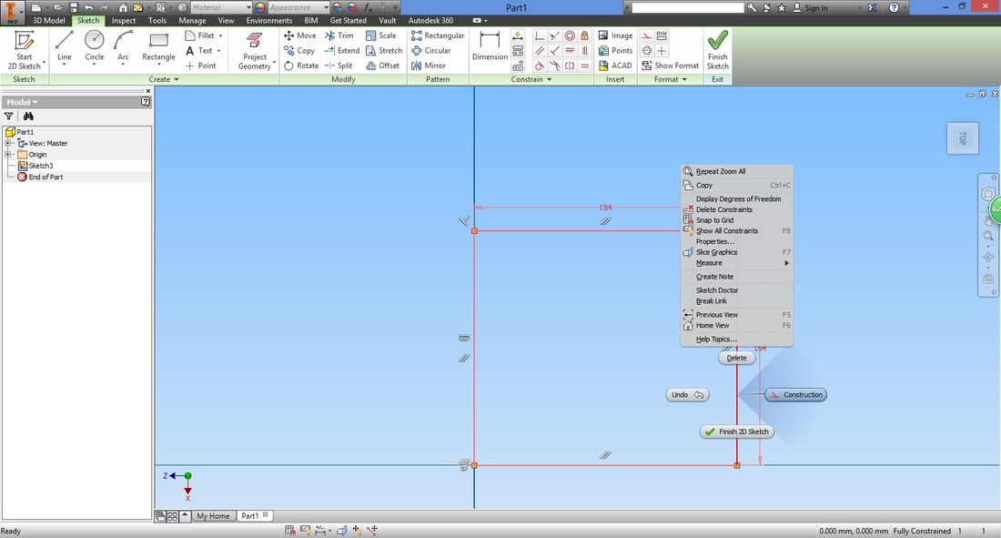
Convert them into Construction lines by right clicking them and selecting Construction.
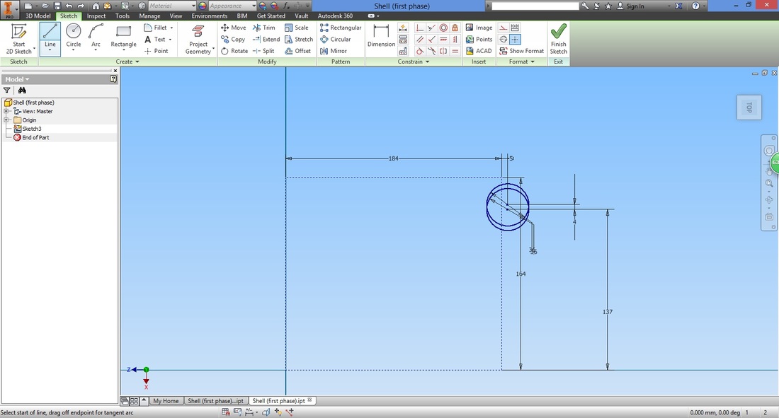
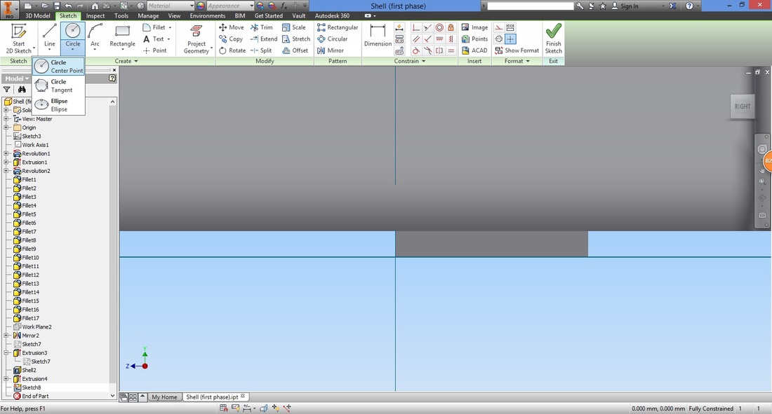
Select the Circle function.
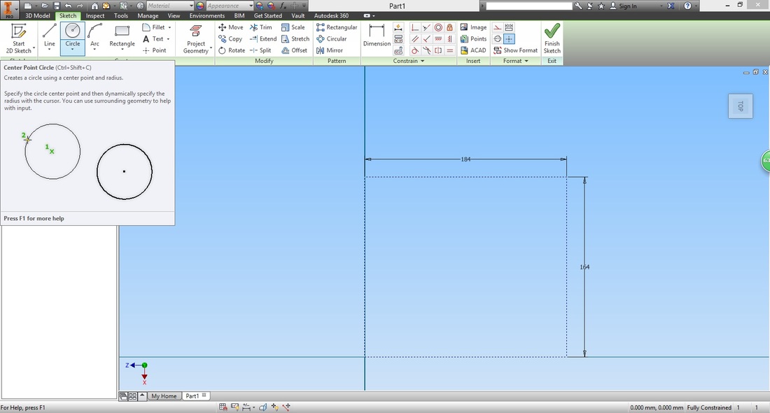
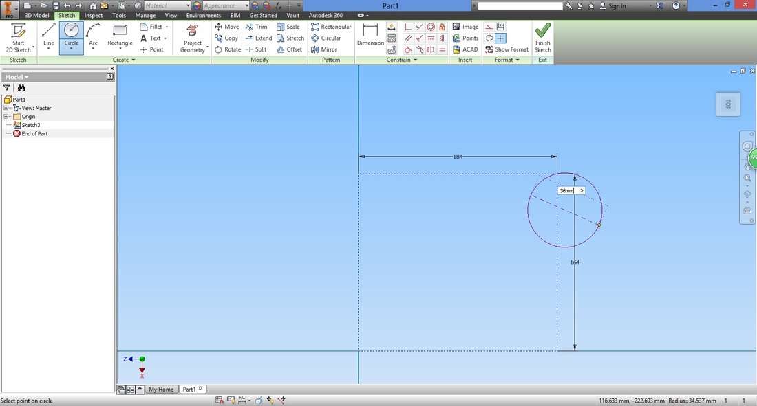
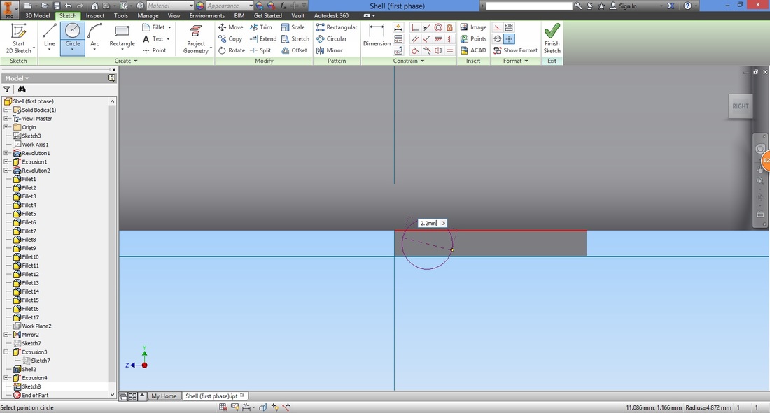
Select any start point on the right of the rectangle.

Key in the diameter.
Repeat for another circle. This time move it's origin slightly above the first circle's origin.

You should have two circles like shown.

Next we ensure both origins are along the same line.
Select the Horizontal Constraint function. 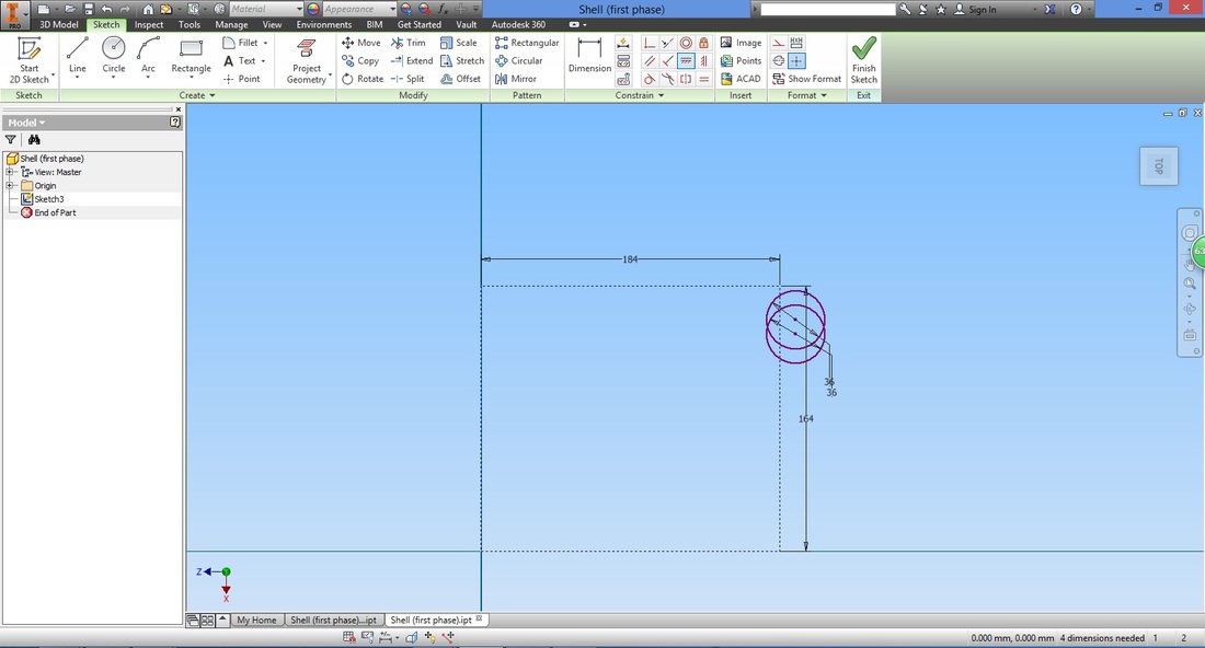
Select the centre of both circles. A dotted line will appear to shown you the line the origin is along.
With the constrain we completed, if one circle is adjusted, the other will follow suit to ensure both origins are aligned.
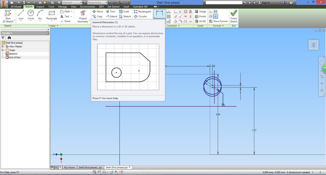
Select the Dimension function to align the circles accordingly.
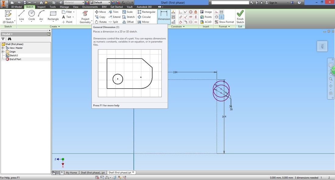
Dimension the circles as shown.
Select the Line function.
The length of the line does not matter as we will trim it shortly.
Ensure that the line runs through both circles as shown. 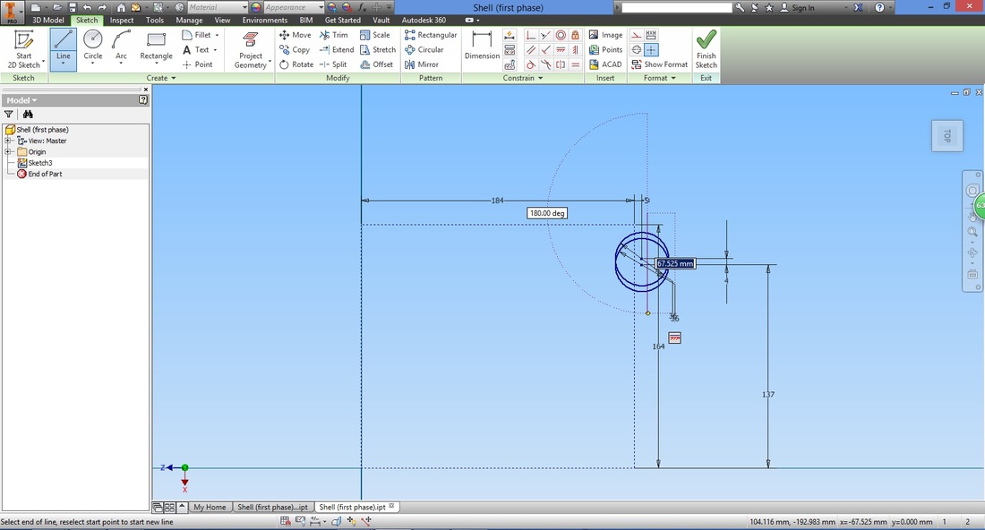
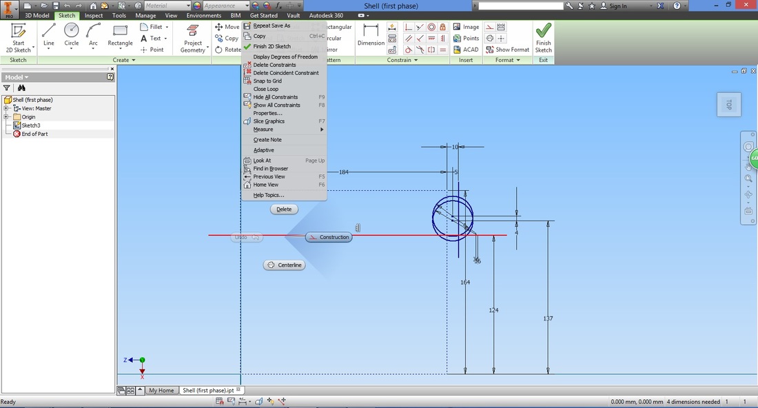
Create another horizontal line. This line will act as the axis later on, hence its length does not matter.

Use the dimension function to position both lines accordingly.
Only two dimensions are required.
To tidy up, make the axis into a construction line by righ-clicking it and selecting Construction.
Select the Trim function to remove lines to where it is connected to another point or line.
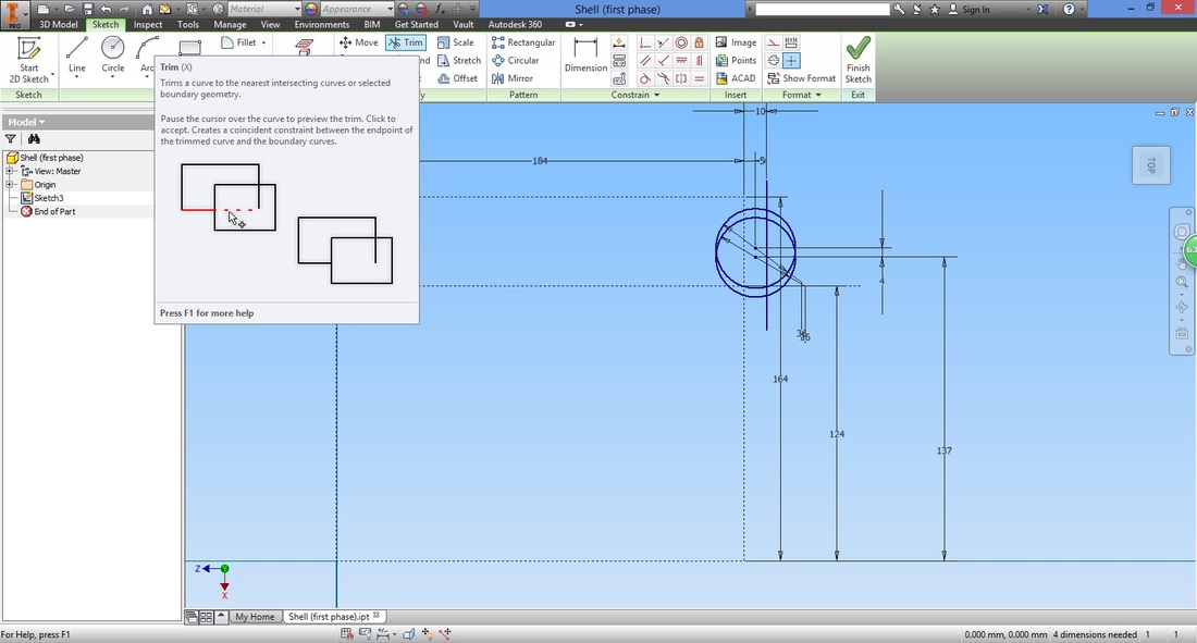
Trim them based on the sequence shown below.
This will be what remains.
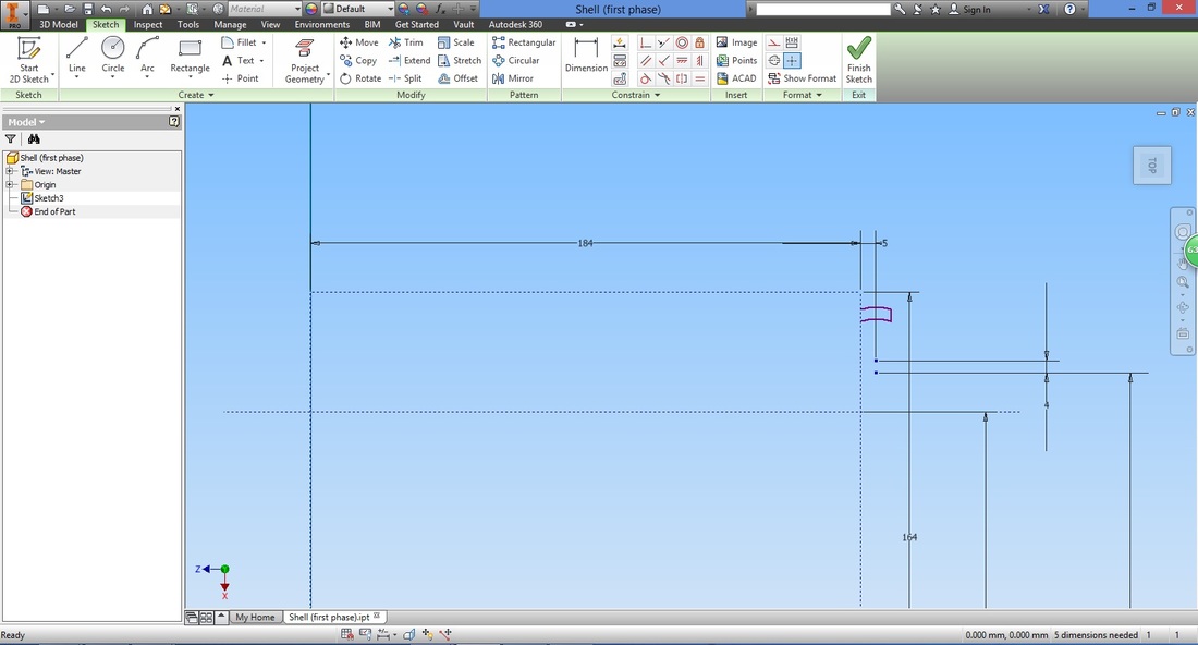
Step 5Select the Line function.

Join the two left points of both curvatures together to close the open profile.

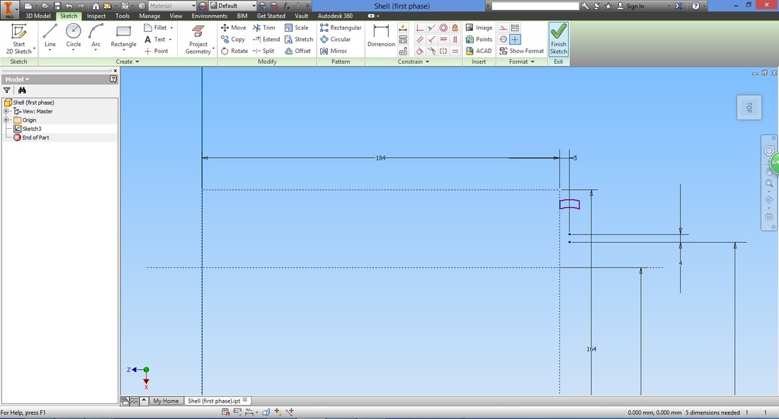
Select Finish Sketch.
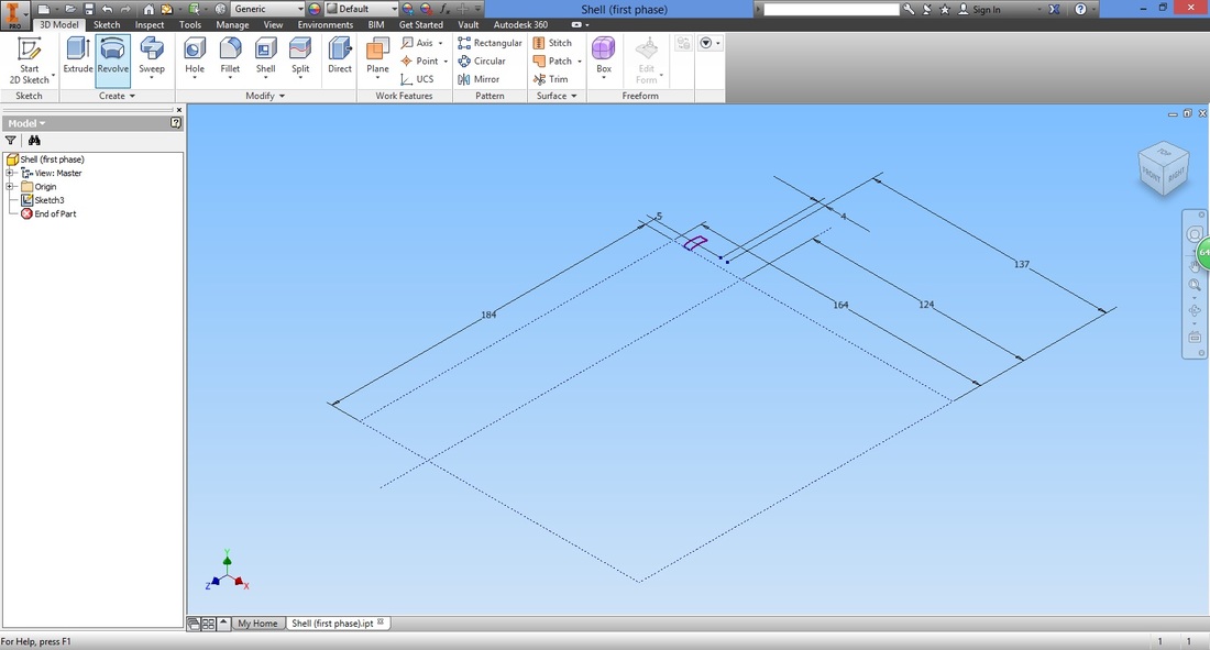
If you recall the Tyre example, we will now create the axis from the sketch line rather than using the line as an axis directly. Select the Axis function, then the line we sketched for the axis.
When we need to use an axis more than once, and out of good habit, use the axis function to create an axis that will be available throughout your designing process. 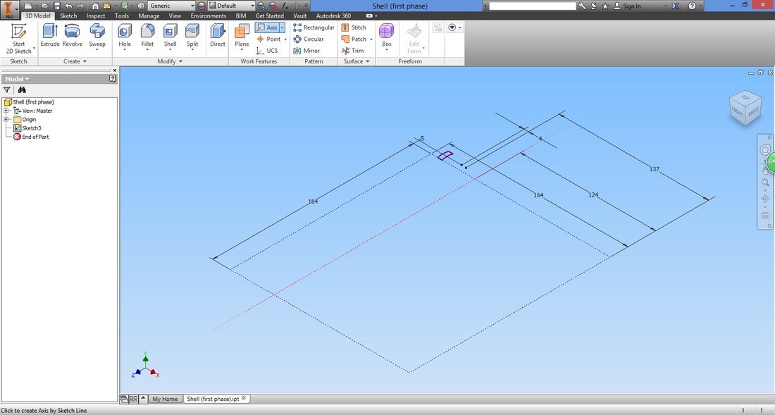
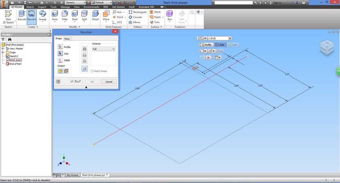
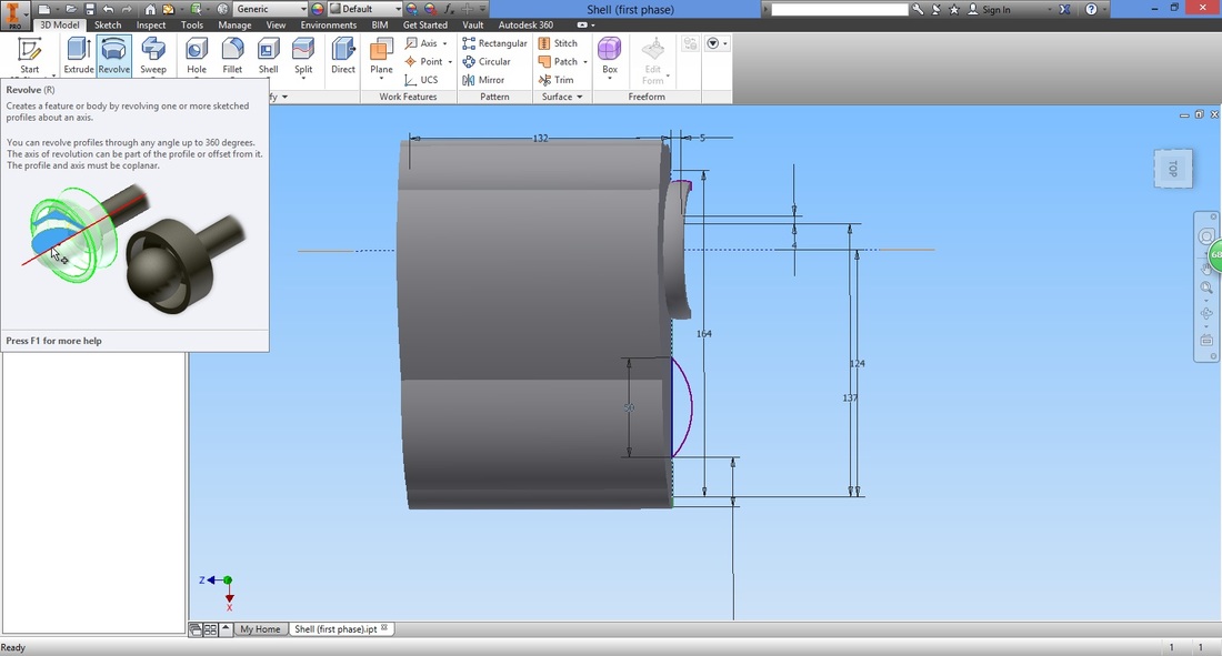
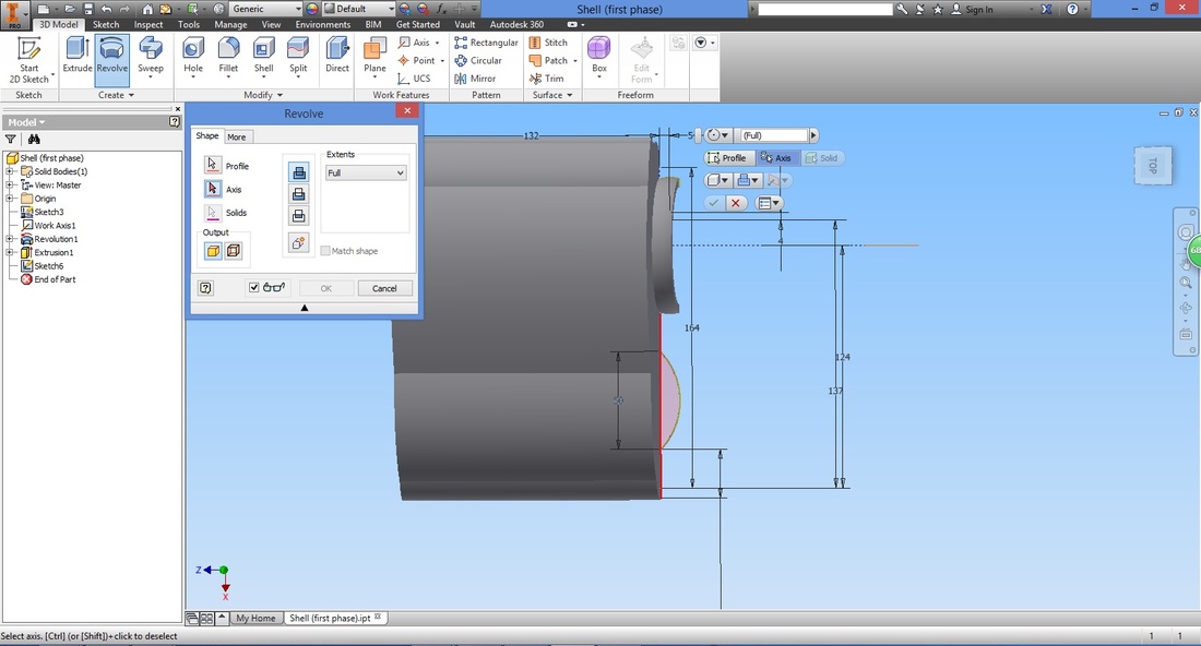
Select the Revolve function.
Select Profile and axis created.
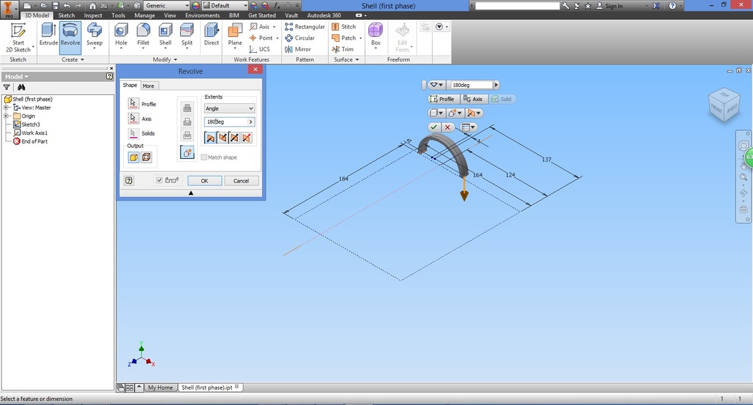
Configure the settings. As we are creating a rim for the Tyre, we will only revolve it at an angle (of 180 deg).
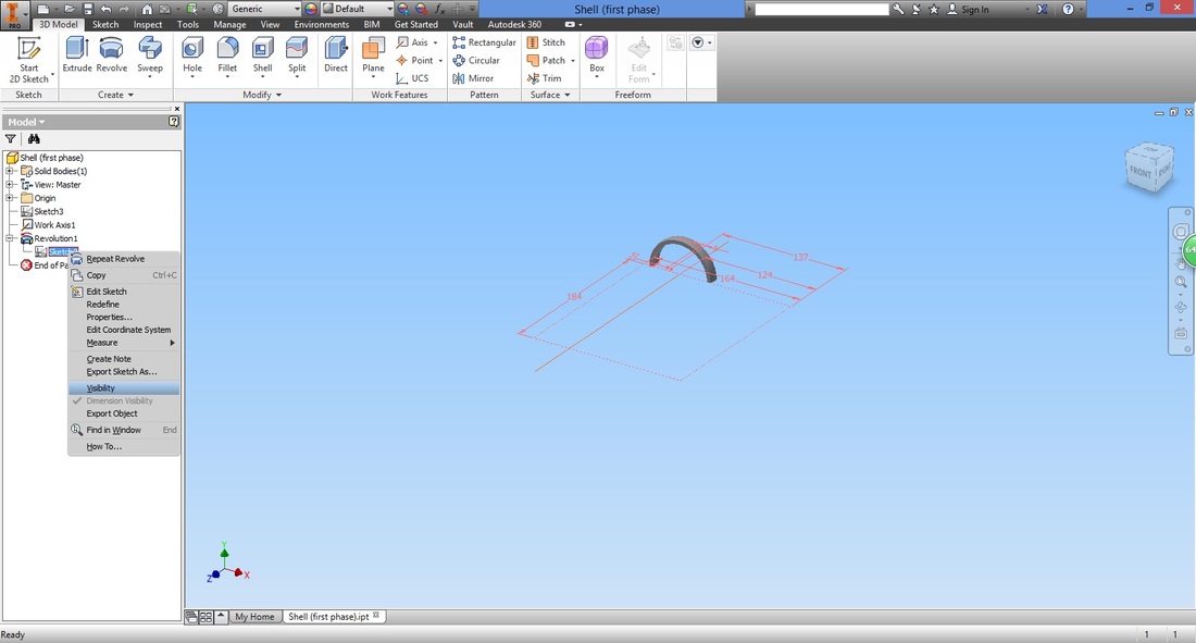
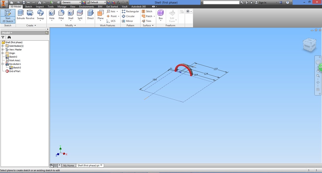
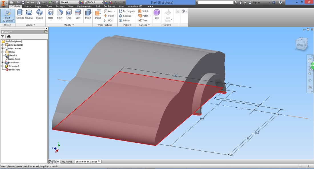
step 6As it is useful for us to know where the base plates will extend, right click the sketch and check Visibility. This is to allow us to continue to view the Sketch.
Select the Start 2D Sketch and highlighted face shown. This is to enable to sketch on the plane parallel to that face.
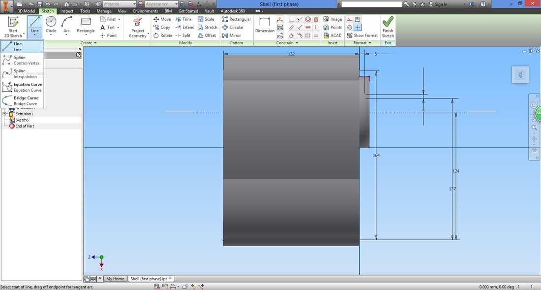
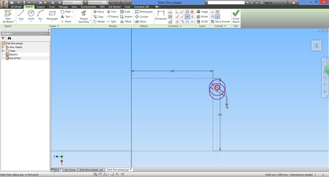
Select the Line function.
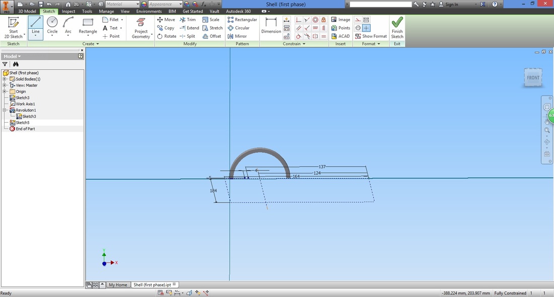
Trace along the origin and create the start point towards its right.
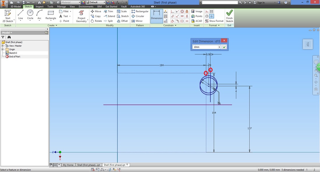
Input its distance. Here the distance used was 10mm more than the base plate. This is because I intended for the shell to extend at least 5mm more on both ends of the base plate set up. Adjust the distance based on your preference. Do take into account the connectors that will be created to mount the cover onto the base plates. 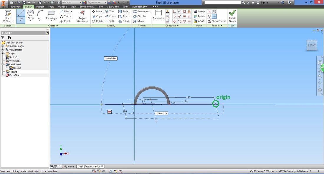
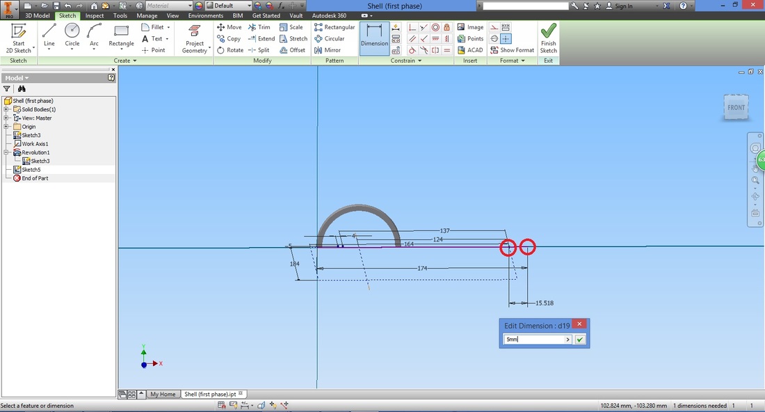
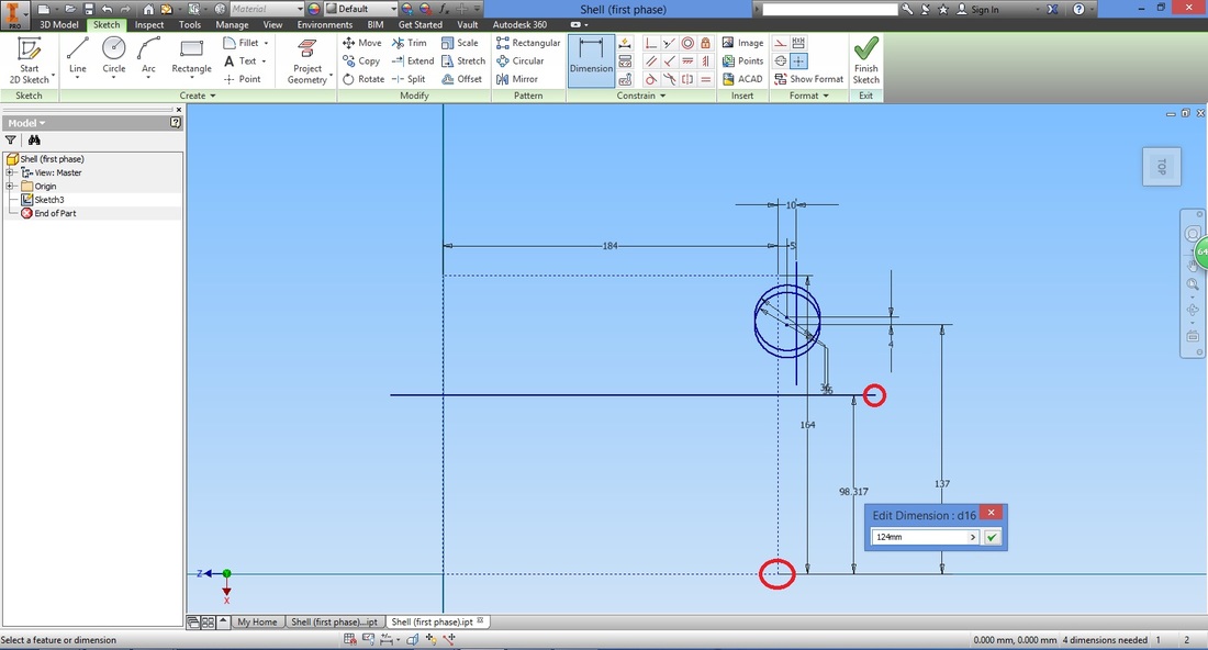
Using the dimension function, distance it from the origin (base plate).
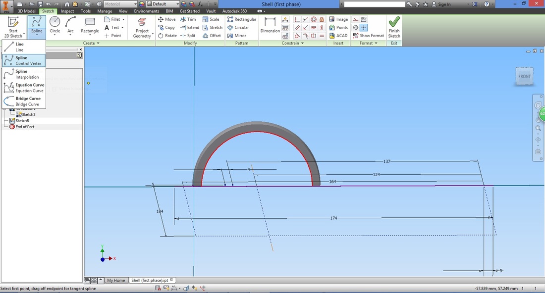
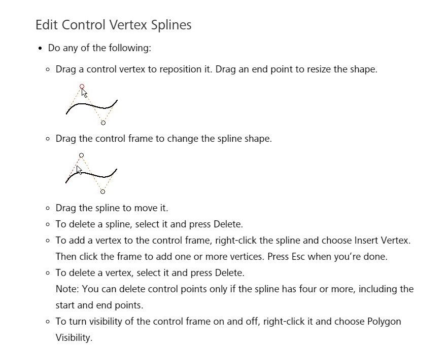
Next, select the Spline (Control Vertex) function. This function allows you to draw a curve that does not require a radius input. Some find this more simple than the Interpolation Spine function. Both can be used, so you may choose based on your preference.
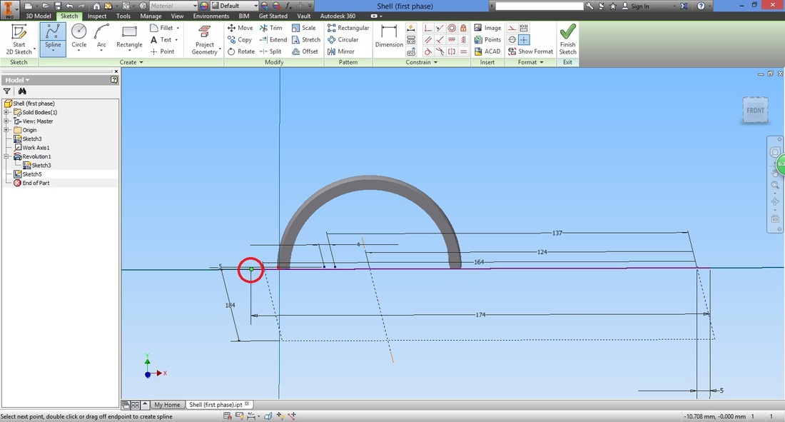
The Start point is as circled below.
Select the point which will act as the midpoint of the curve. This can be adjusted later on as well.
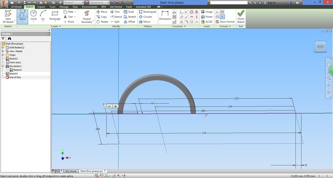
The next point selected is the end point of the spline.

Continue using the spline function to draw the side view of the vehicle.
The most important thing to note is that the sketch must be a close profile. 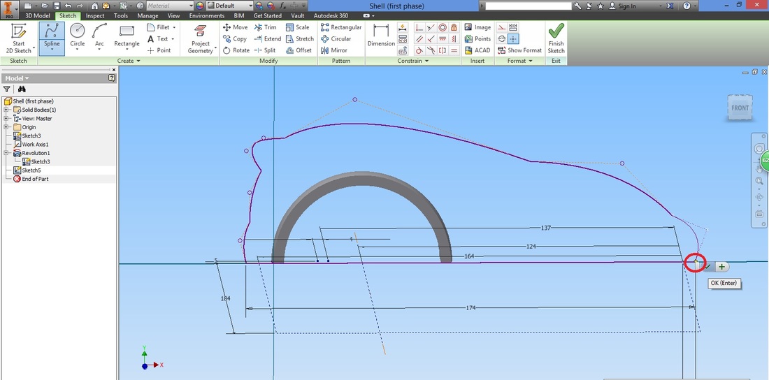
You may follow the example below or create the vehicle based on your own creativity.
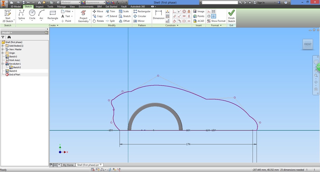
Once completed, exit sketch.

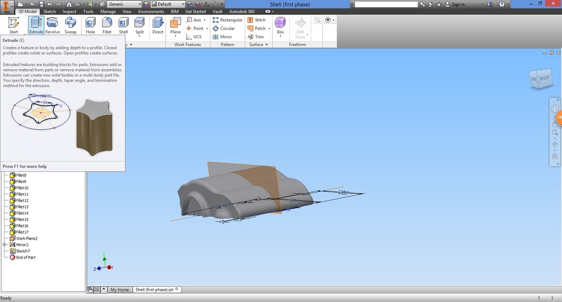
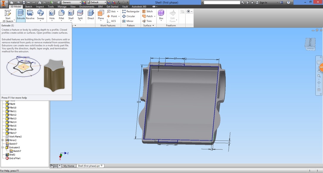
Step 7Select the Extrude function.
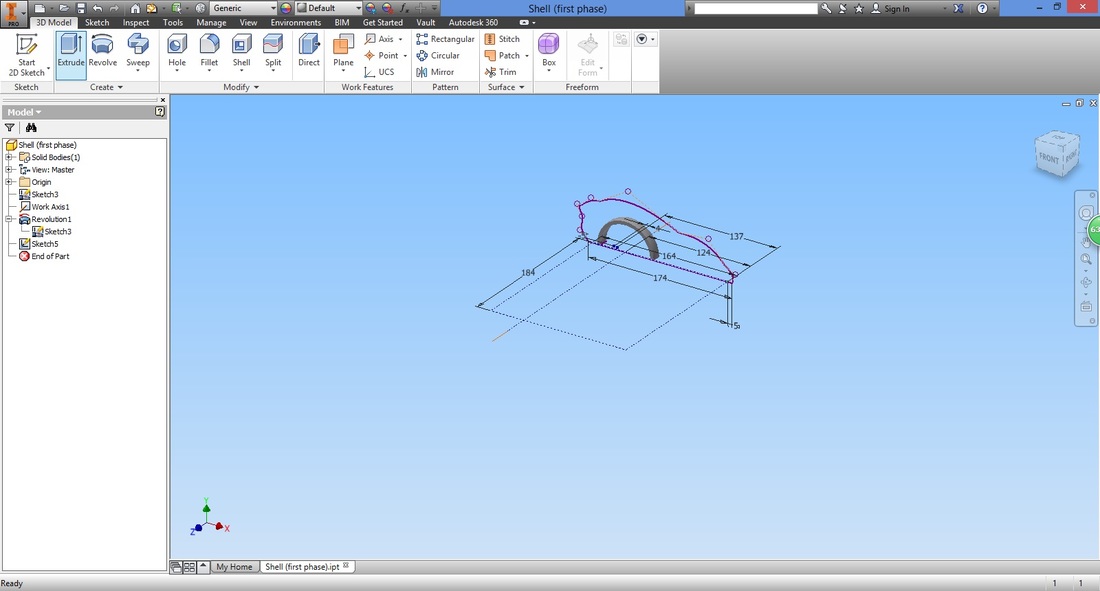
Select the profile.
If the profile is not closed, it would not be able to be selected. 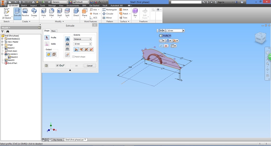
Configure the settings.
The extrude distance should only be half the size of the desired vehicle as we will be using the mirror function. 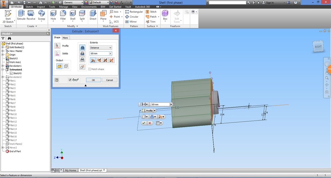
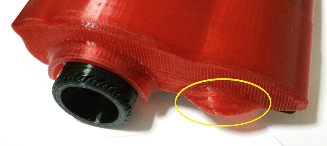
step 8As two castor wheels will be used, it would not require a wheel rim as per the previous one. Hence, here we draw a quarter of a sphere to enable the cover to look more AESTHETICALLY pleasing.
Select the Line function.
Input the length.
Recall that we need a closed profile hence this line is required, other than the arc. 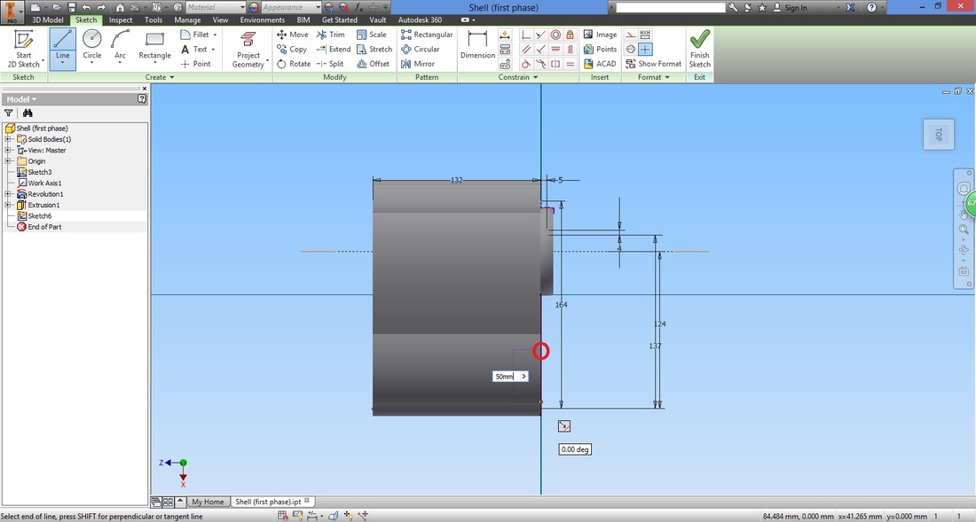
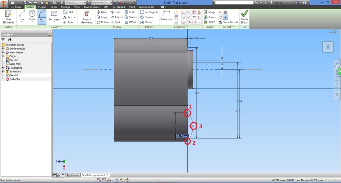
Select the Arc (three point) function.
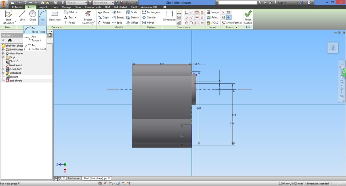
Select the Start point, End point then the Mid point (or arc height).
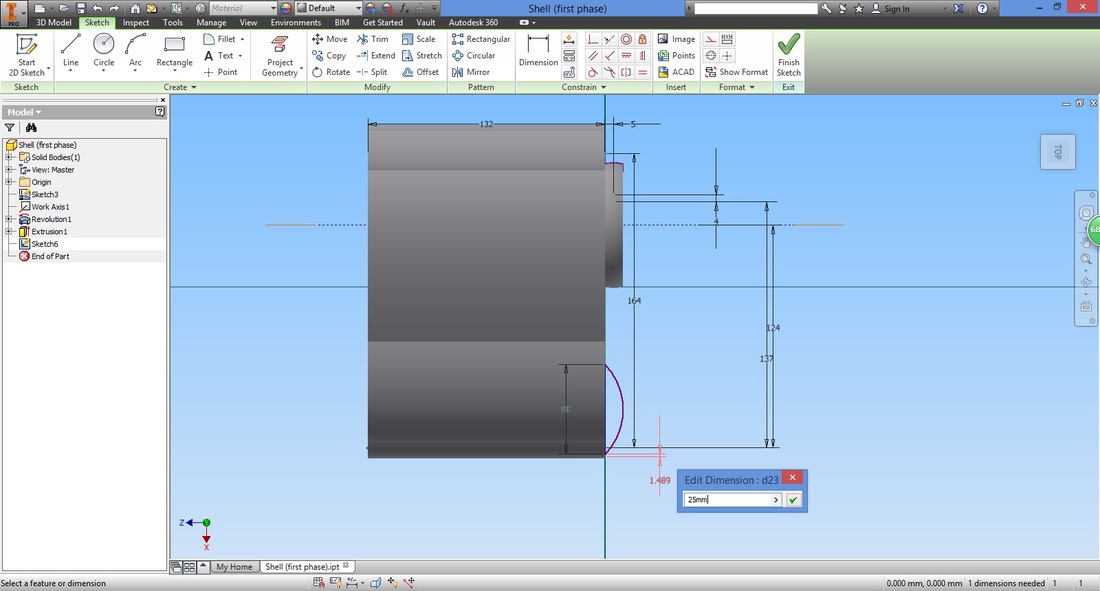
Next, use the Dimension function to shift it to the position desired.
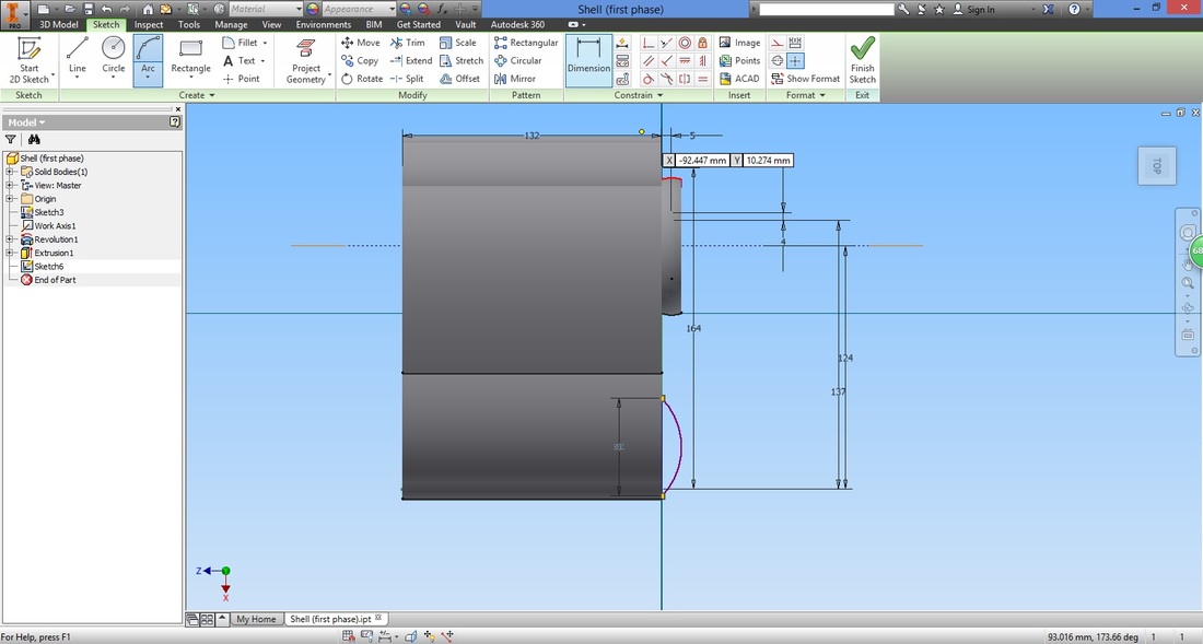
Here I moved it back 2cm.
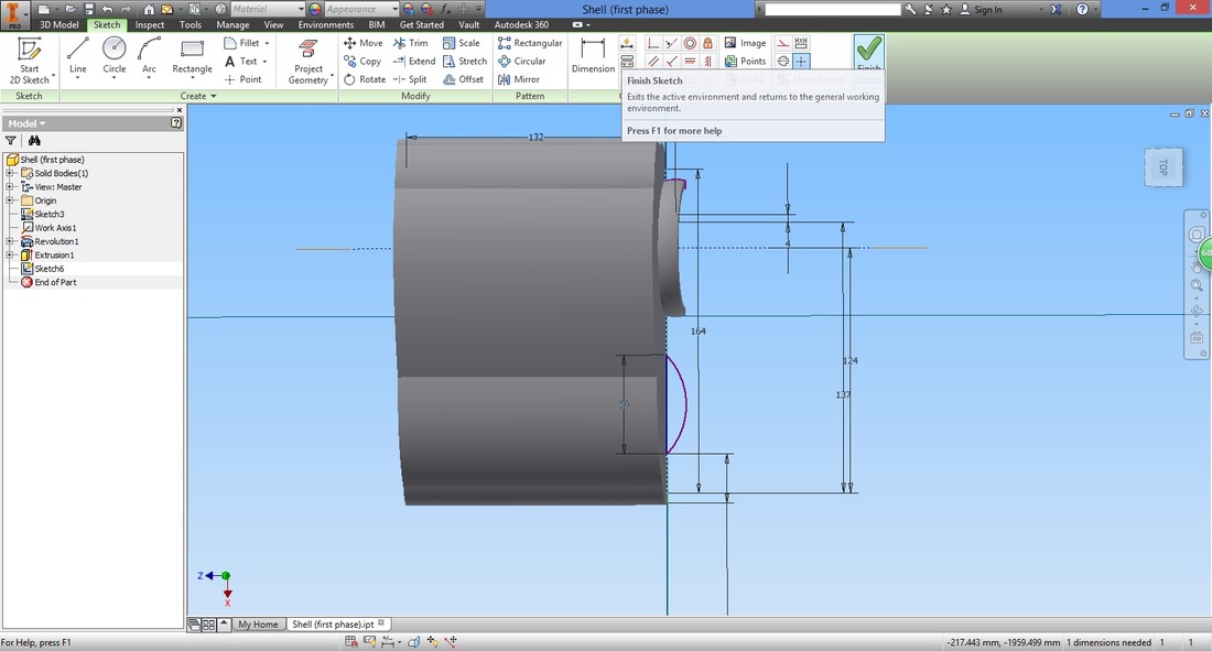
Once completed, select Finish Sketch to exit.
step 9Select the Revolve function.
Select the closed profile.
Configure the settings.
Select Angle under Extents type and key in the angle the profile is to revolve. 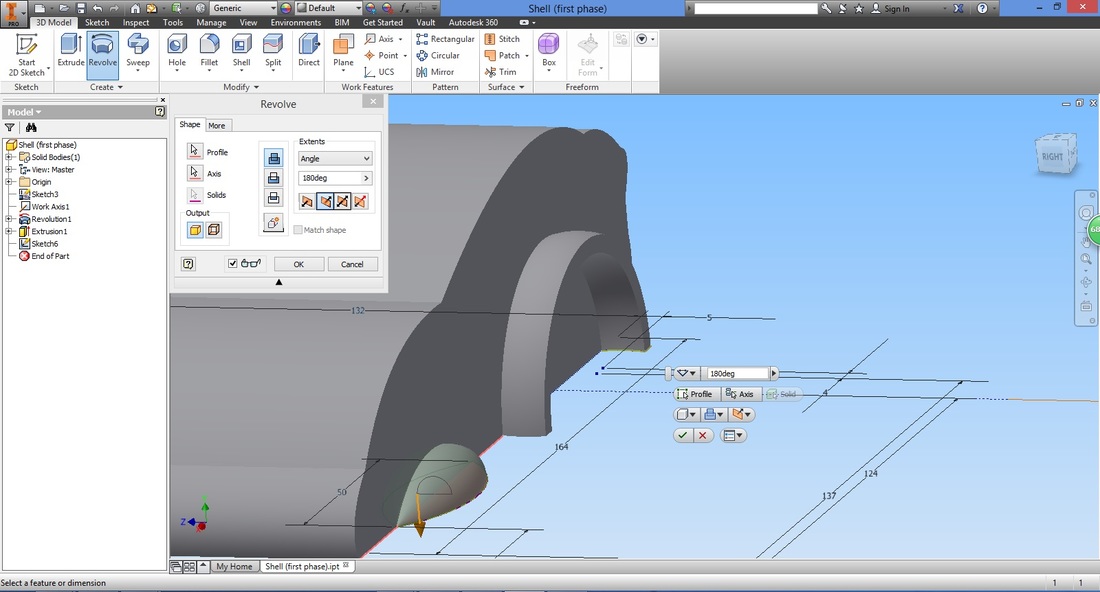
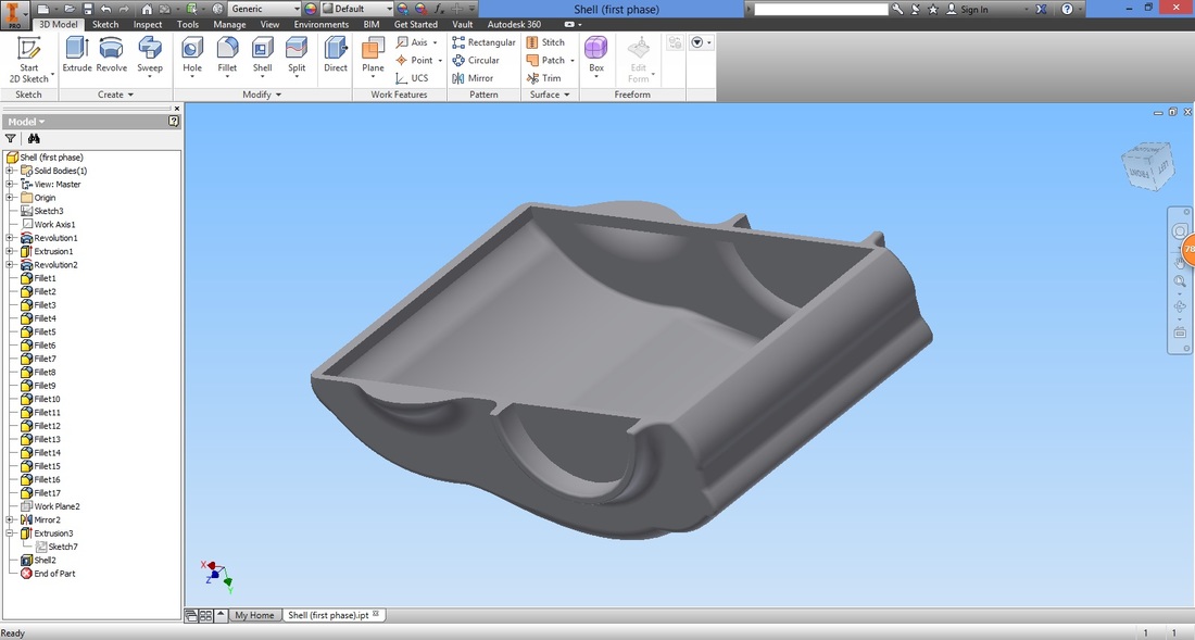
You will have something like this.
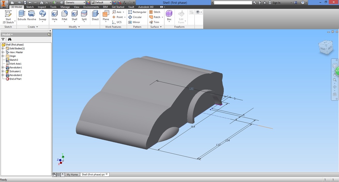
Step 10Left-click the edges between the parts.
Select the Create fillet function to fillet the edge so that it would be smooth. 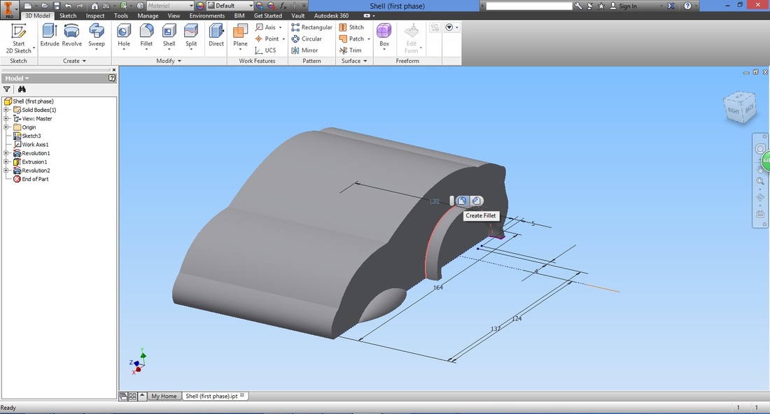
Input the fillet desired. This input values will ultimately affect the shape of the vehicle.
If the input value is too large, the feature will not be accepted. 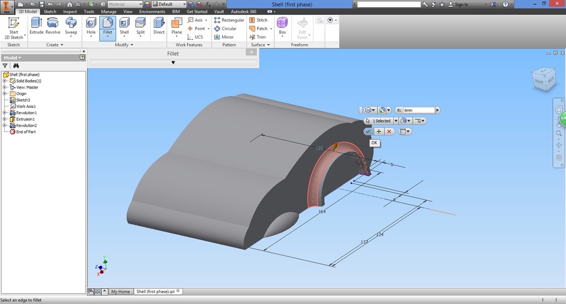
Continue with the remaining edges.
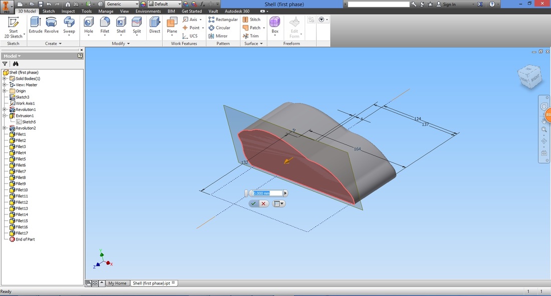
You can refer to the slideshow in sequence to ensure no edges are missed out. Step 11Select the Offset from Plane function to create the plane to mirror the part.
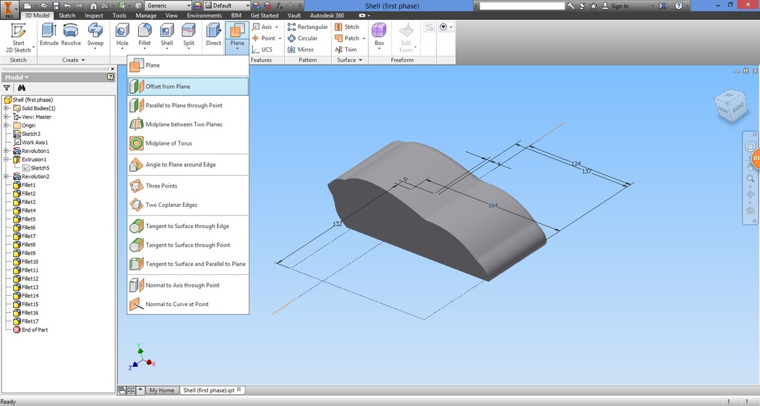
Select the cross-section face and set the offset to zero. This is to enable the plane to be on the face.
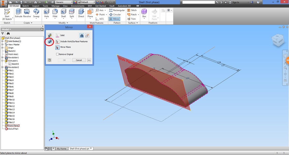
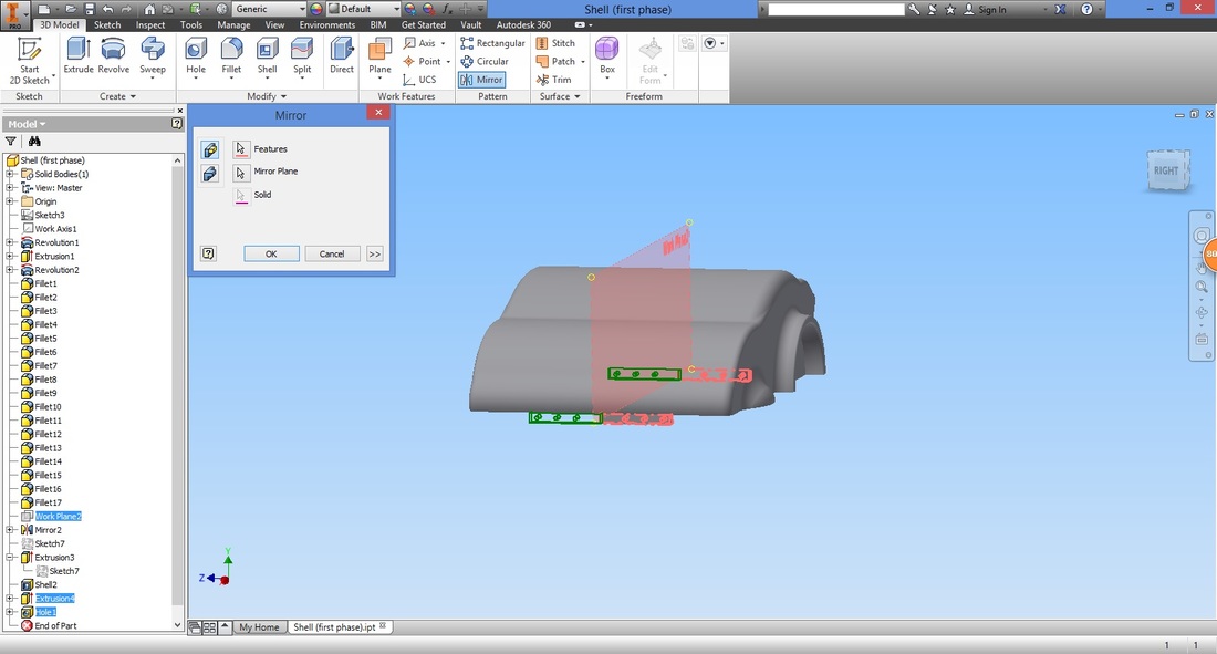
Select the Mirror function.
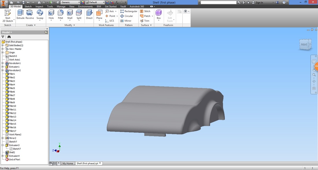
Select the body rather than the feature mirror type. This will enable the whole body (including the fillets) to be mirrored without having to select one feature at a time.
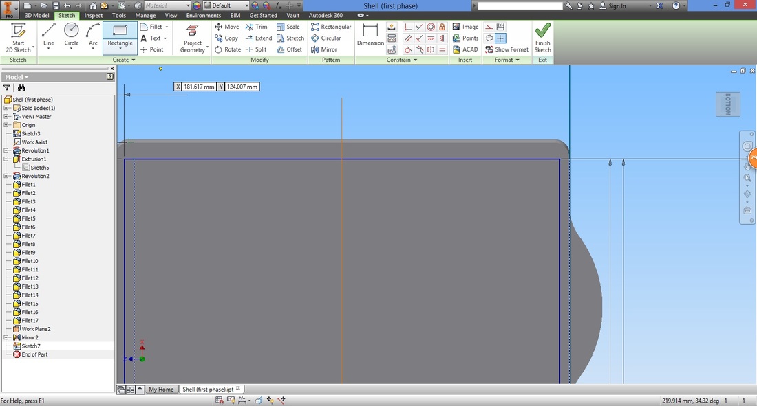
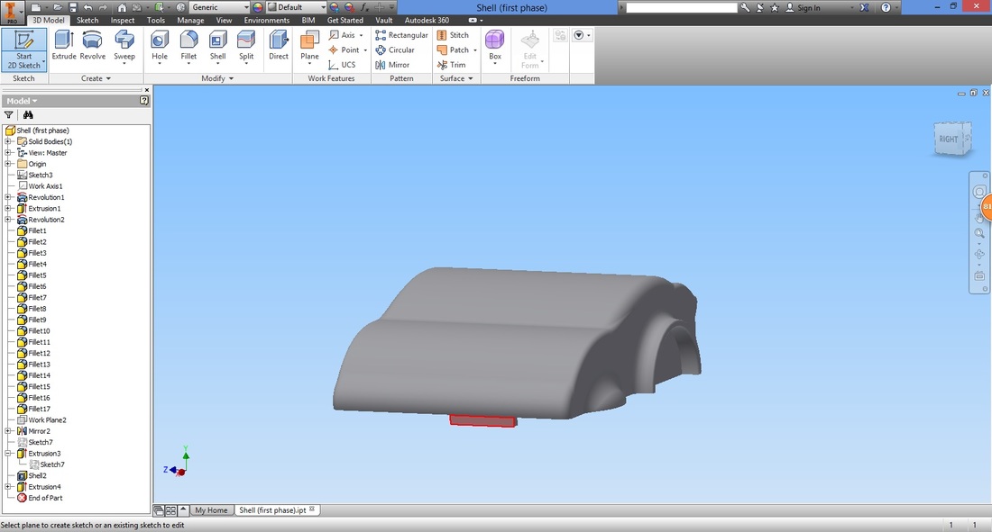
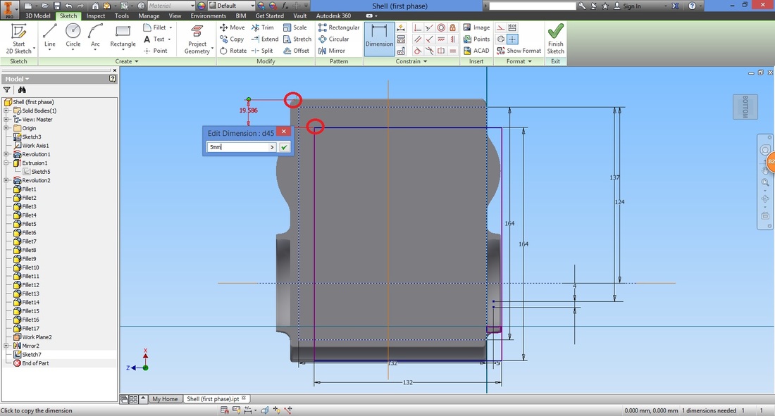
STEP 12Select to create a sketch at the bottom of the cover.
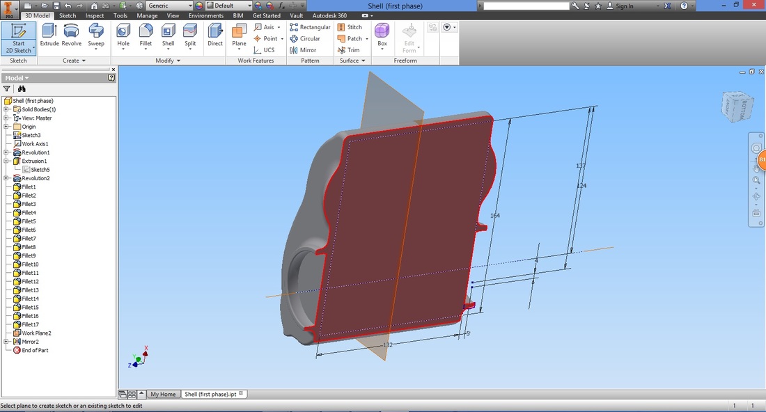
Select the Rectangle function to create a rectangle.
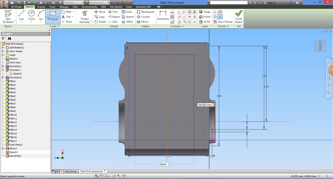
Use the Dimension function to align the rectangle.
This rectangle will be the area emptied hence sufficient space is required along the sides as it will act as the thickness of the cover.
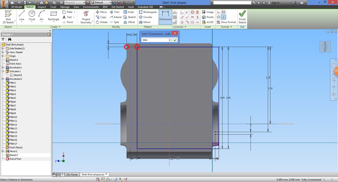
Select Create Sketch function.
The start point should be along the mirror plane.
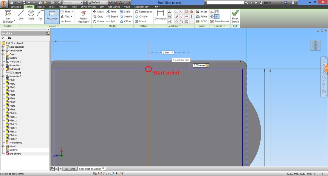
Repeat another rectangle below.
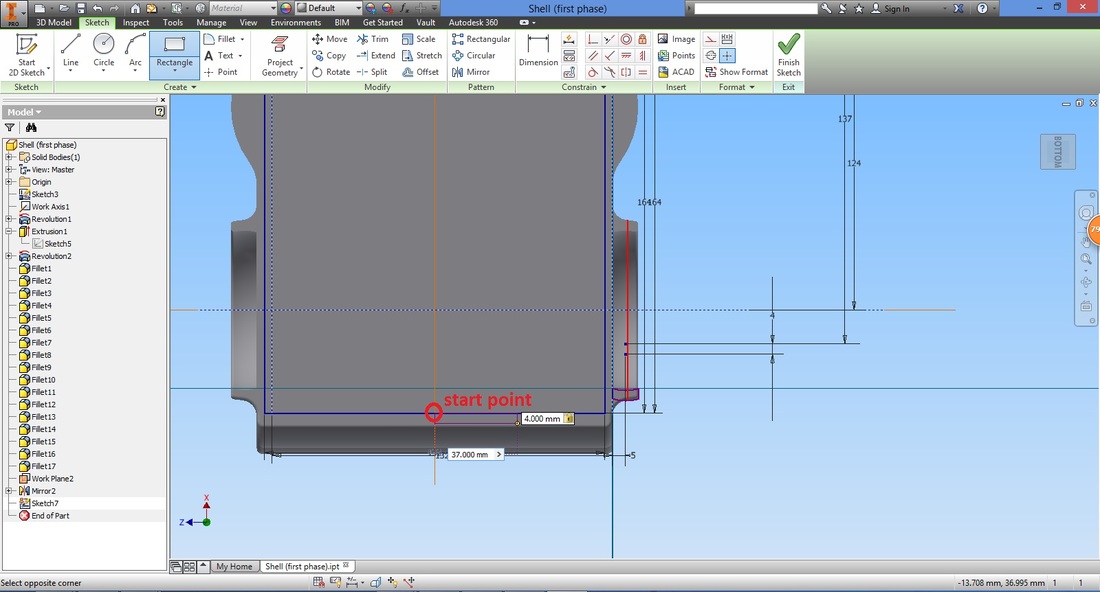
Once completed, select Finish Sketch.
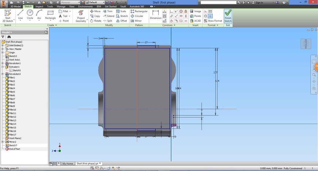
step 13Select the Extrude function.
Select the profile and configure the settings.
By cutting the solid slightly, the Shell function can then be used. 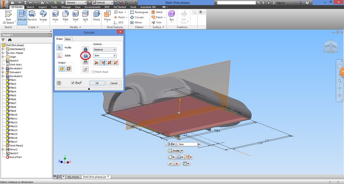
Select the Shell function.
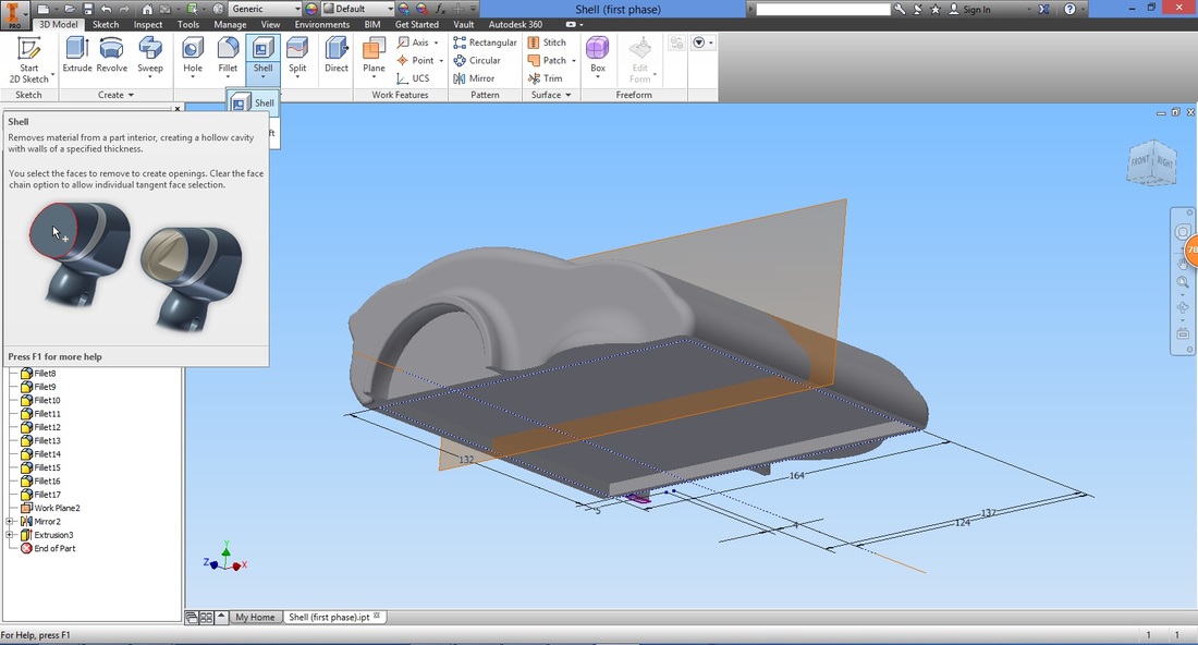
Configure the settings as shown.
The input of the shell thickness should be printable by the 3D printer. 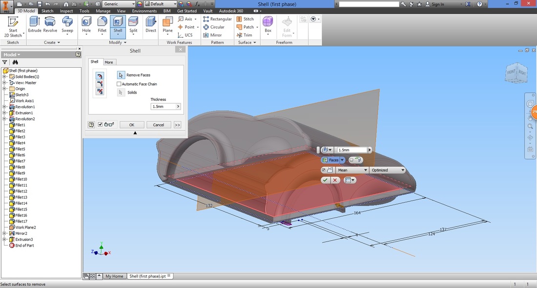
The part will be hollow as shown.
step 14Right click the sketch in the Model plane and select Share Sketch.
This is to allow the sketch to be used by other features. 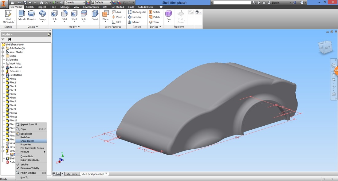
Select the extrude function.
Select both profiles to be extruded.
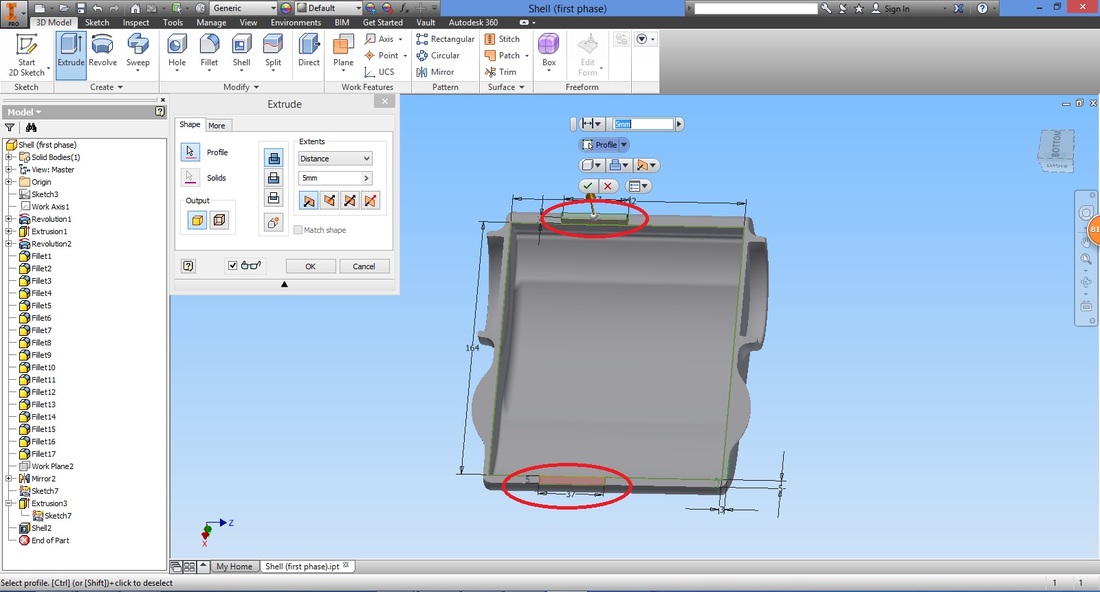
It should be extruded like this.
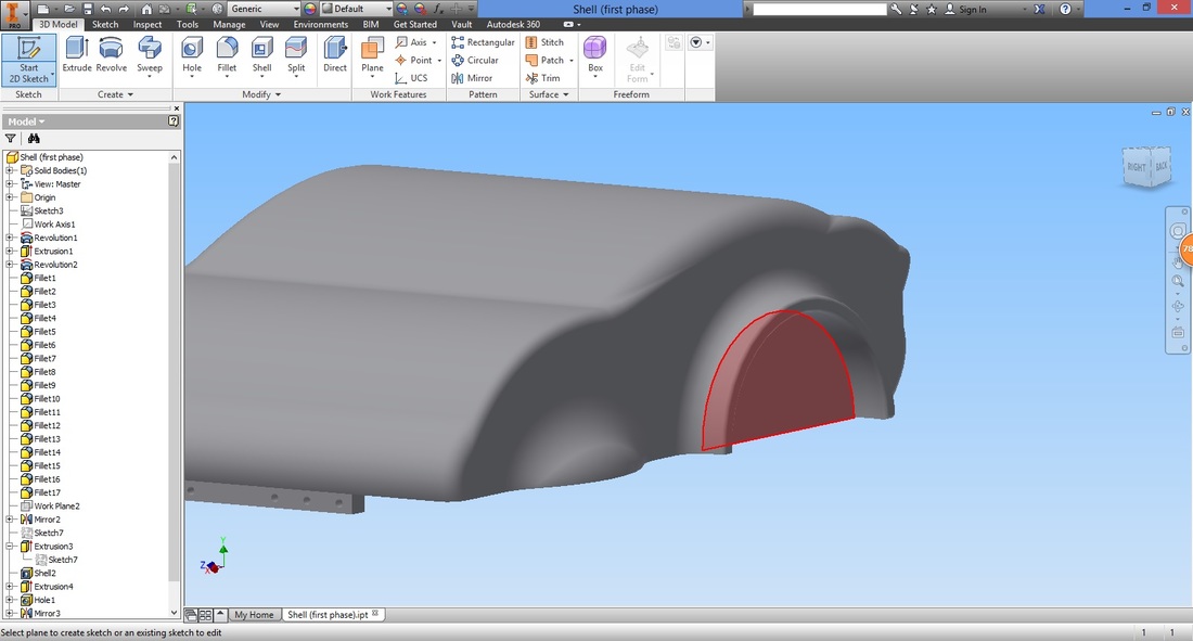
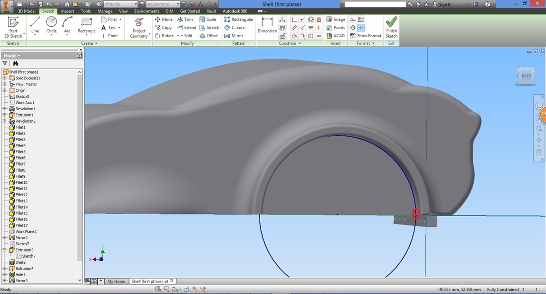
step 15Select the face shown to start the 2D sketch.
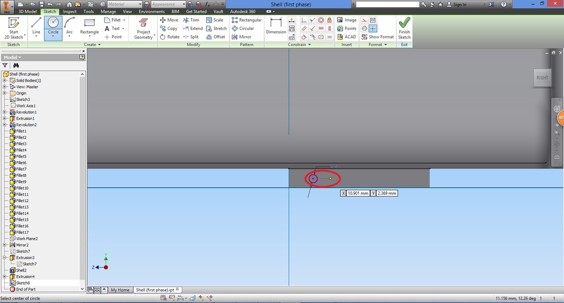
Select the Circle function.
Draw a circle. (It will be positioned using the Dimension function later on).
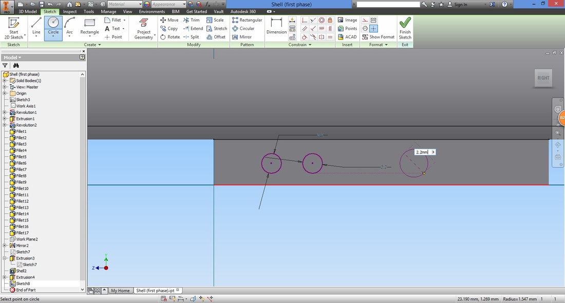
Draw a second circle by tracing (without clicking) the centre of the first circle. Left click on the right.
Repeat for a third circle.
Select the Dimension function.

The function is repeated to arrange the circles.
To align the centres of the circles, select the Horizontal Constraint function.
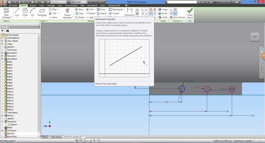
Select the centres of the circle in pairs (one after another).
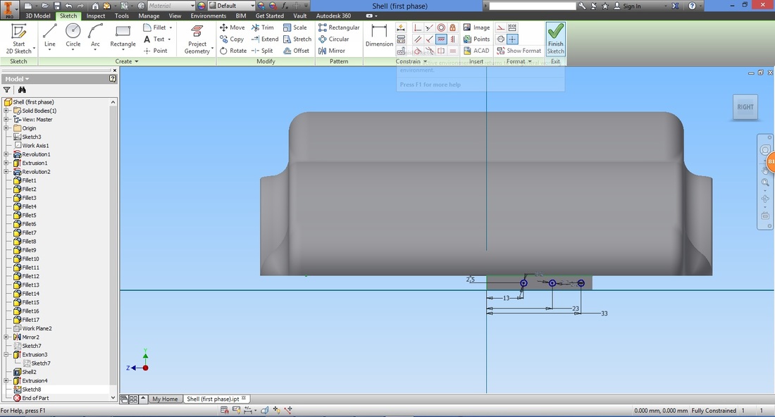
1st and 2nd; 2nd and 3rd circles Exit sketch using the Finish Sketch feature.
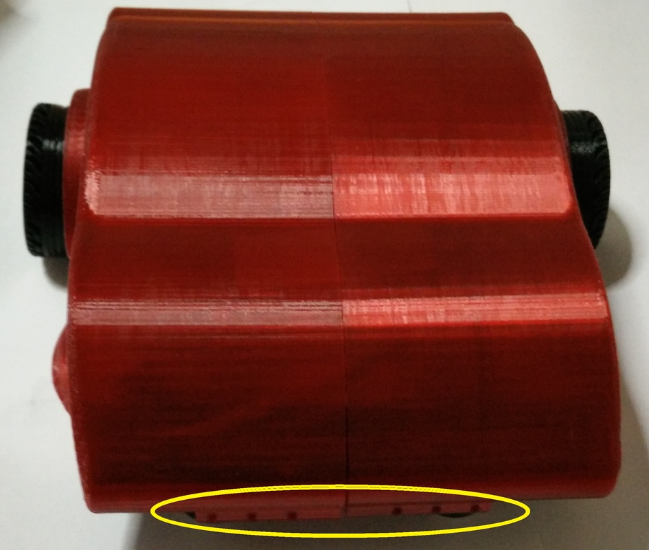
step 16Select the Hole function.
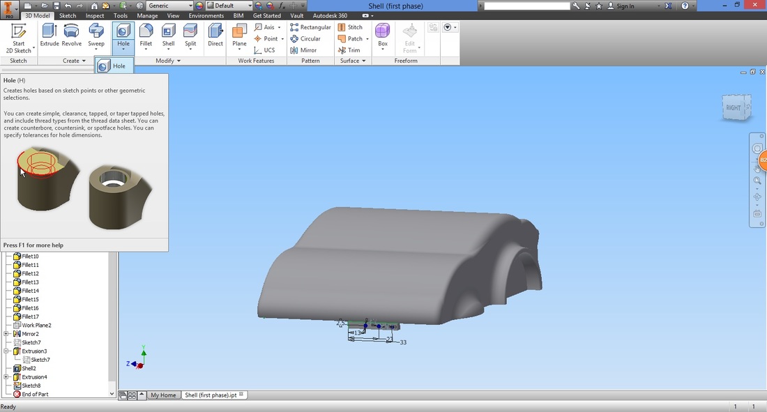
Select the centres of the circles.
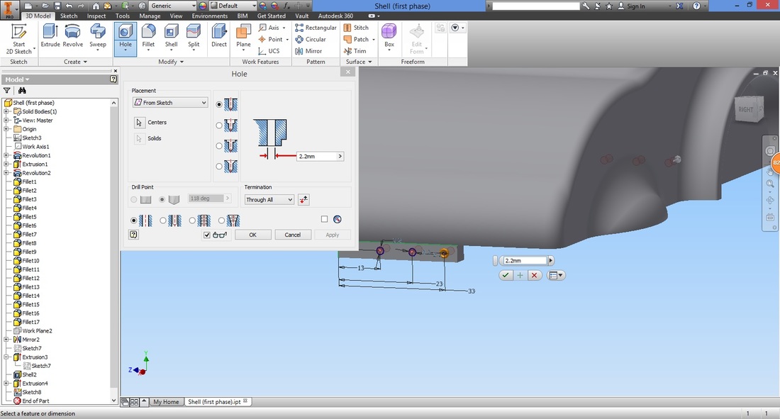
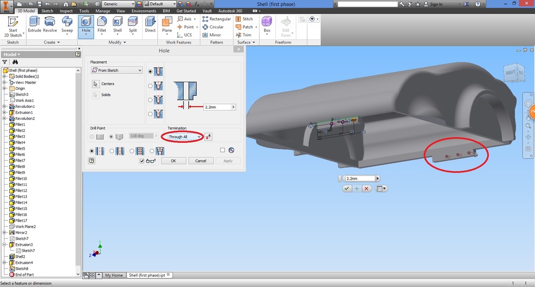
Select Through All transition type to cut both rectangles.
Select Mirror function to mirror the connector block.
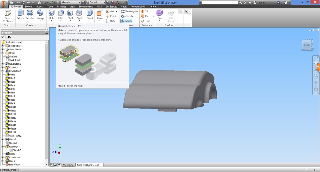
Select the part and feature to mirror.
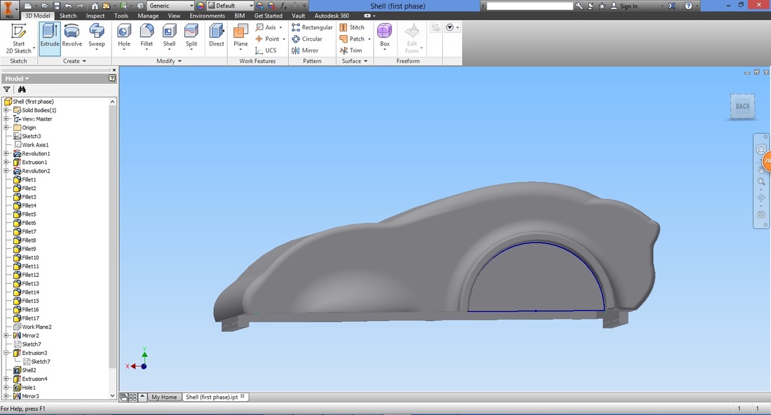
Step 17Select the face shown and start a 2D Sketch. This is to create a sketch for an extrude cut subsequently.
Select the Circle function.
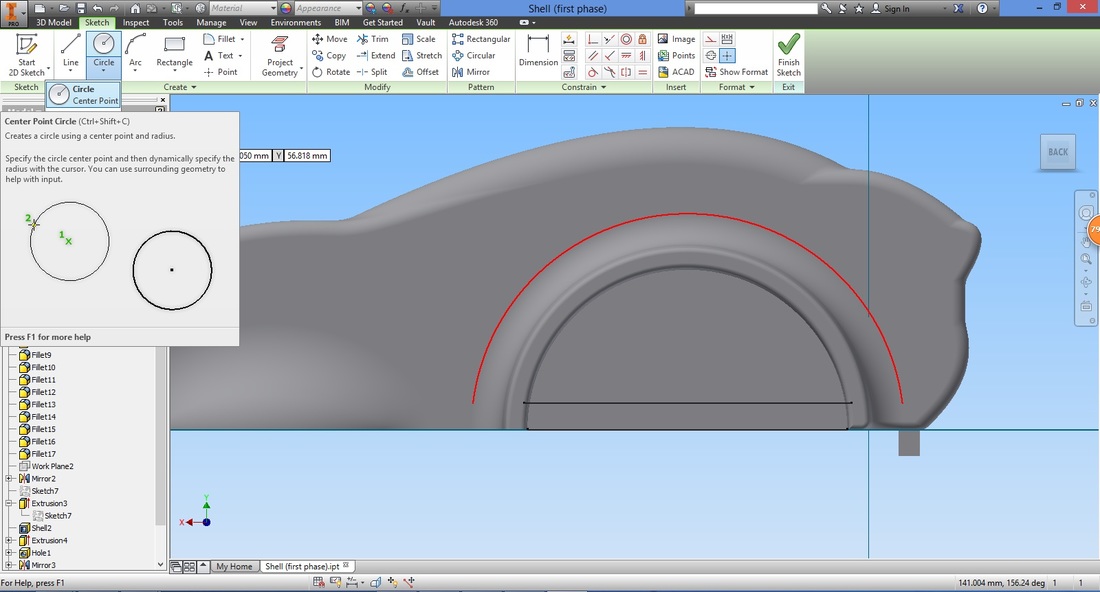
The cursor will turn green when it is at the centre of the circle previously drawn. Left click it.

Left click at the edge of the inner rim. The diameter of the circle is seen to match the first sketch required.
You can rotate the view to double-check the circle drawn.
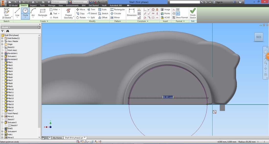
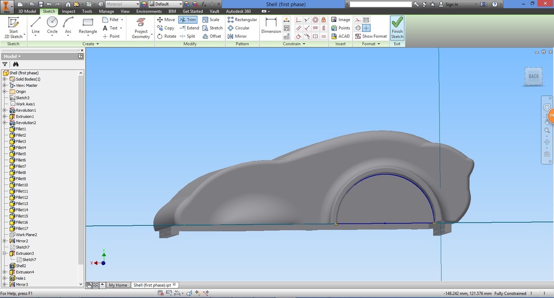
Select a Line function and draw a horizontal line.
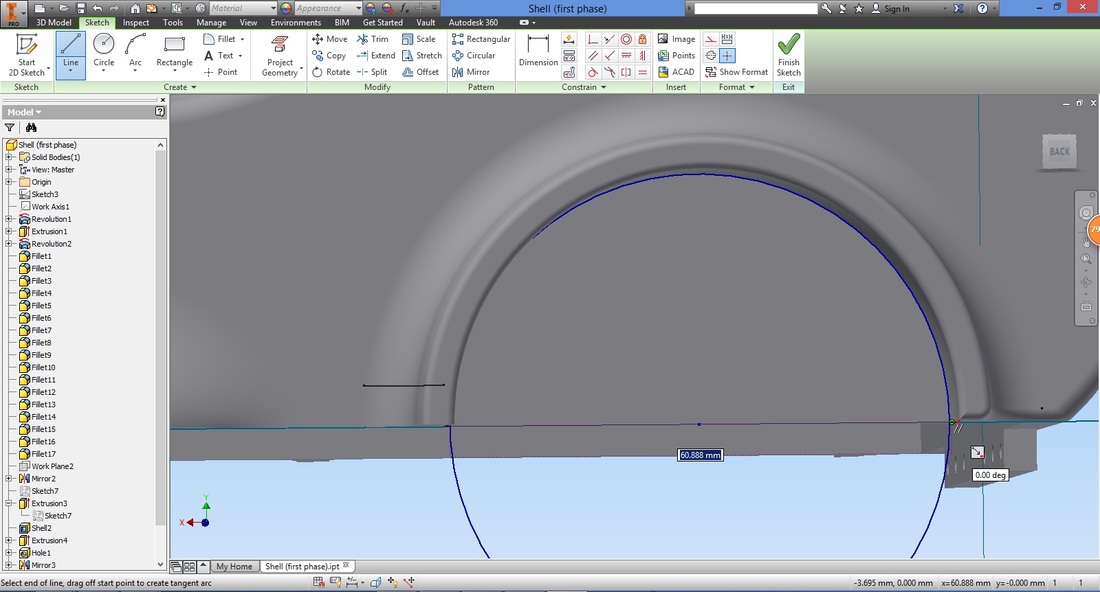
Select the Trim function to trim off the bottom half of the circle.
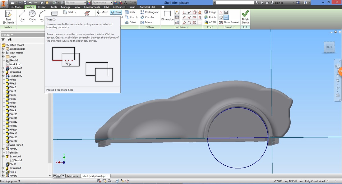
The preview of the trim will be dotted as shown.
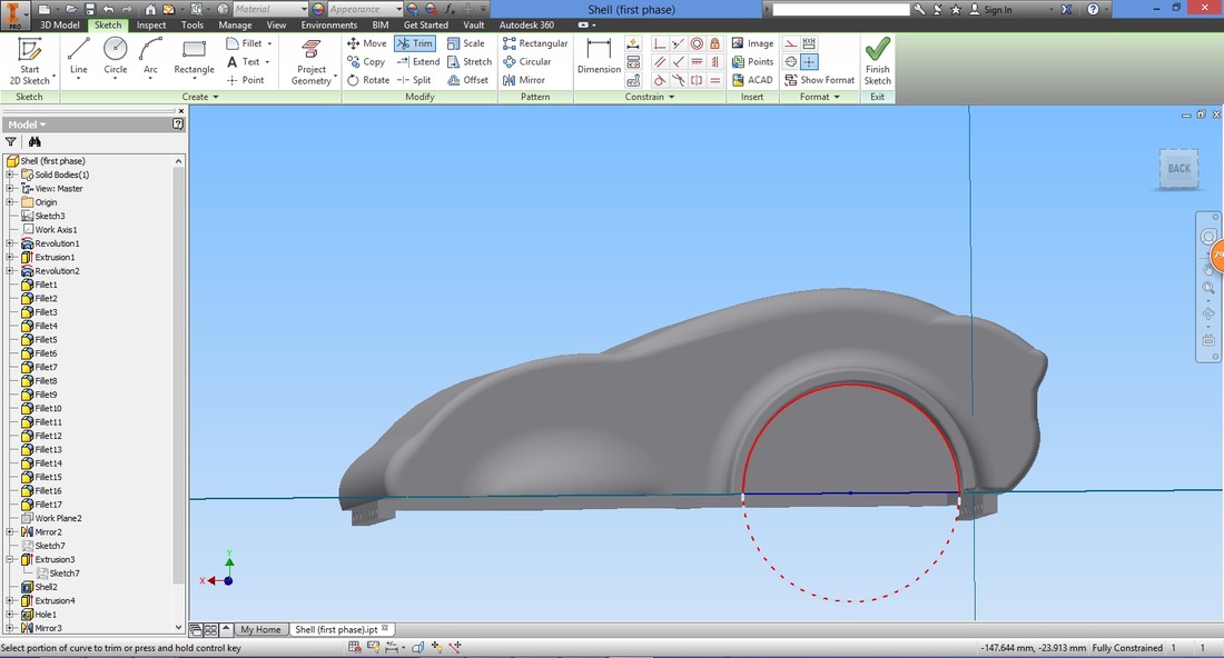
Exit the sketch once complete.
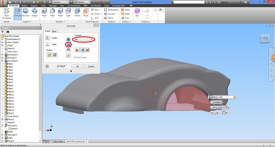
step 18Select the Extrude function.
Configure the settings to Extrude-cut the selected profile.
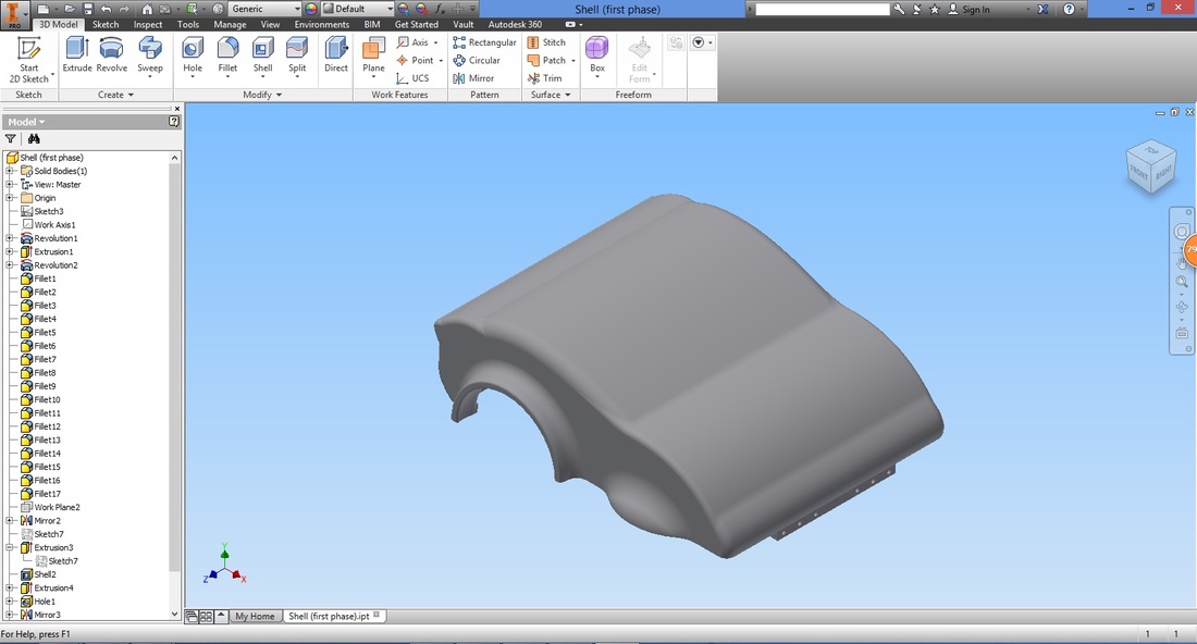
CONGRATULATIONS!
| ||||||||||||||||


Download COVER file |
| ||
