|
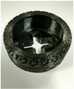
The following is a tutorial to teach you step by step how to create an Tyre using the educational version of Autodesk Invertor Professional. If you have yet to install it, you may refer to the link below.
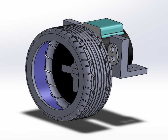
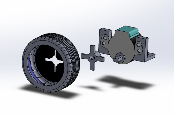
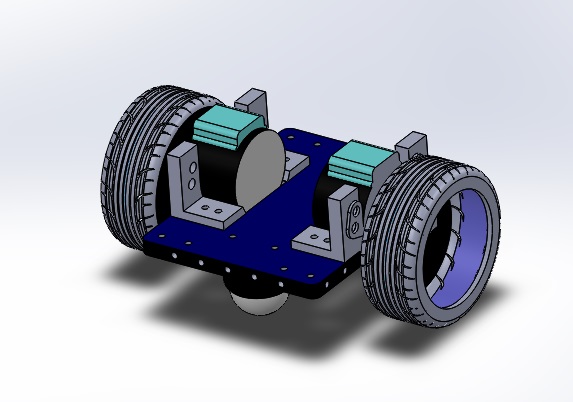
This base plate dimensions were drafted in consideration of the following components:
Here's a few good things to remember before we begin:
As this serves as a tutorial, there are intentional hiccups along the way to give you a better learning experience of what to look out for in the future.
This tutorial was adapted from the one in this video to suit the needs of this project. The main changes are the dimensioning and the cross-section of the tyre to enable for it to be 3D printed & be tough** enough for applications.
tough**: If you follow the design in this video, note that the dimensions may result in the printed threads to be crushed due to it's lack of thickness. As always, be careful not to follow online platforms too strictly as it may not suit your needs entirely. LET'S START!STEP 1Launch Autodesk Inventor Professional.
The homepage will appear as shown below. Select PART to create a new part. WHAT IT MEANS: 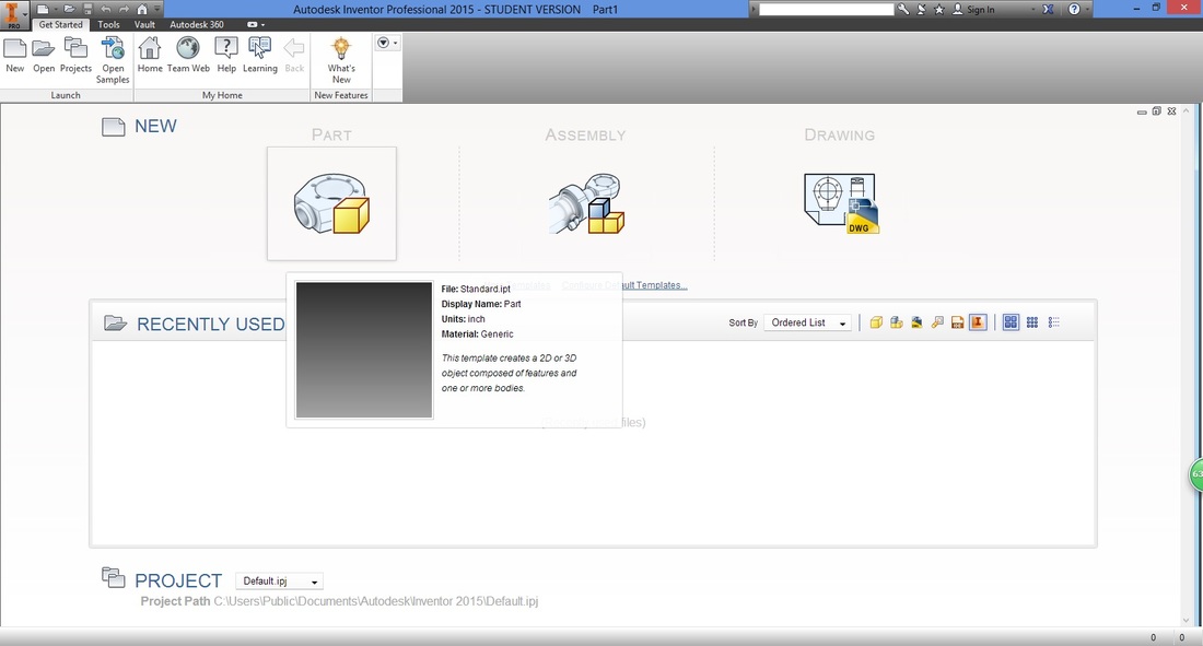
STEP 2 (IMPORTANT)A good habit to have is to check and set the dimensions of your drawings.
Under the Tools ribbon, select Document Settings. 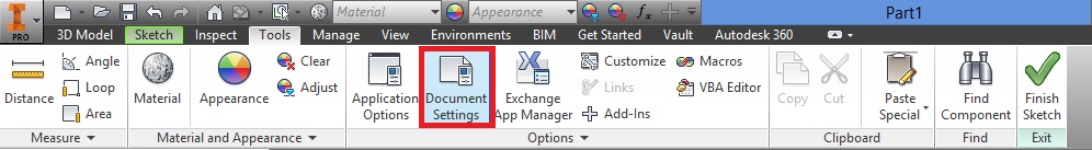
A window will then appear.
Select the Units tab, and adjust accordingly. 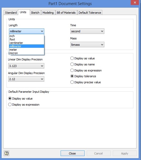
Select Apply then Close, to apply settings.
STEP 3In the 3D Model ribbon, select "Start 2D Sketch".
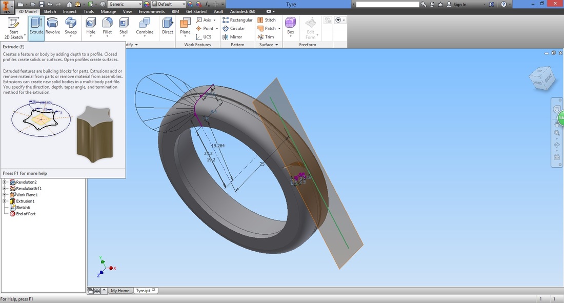
Notice that if you hover over the function for long, a quick introduction of the function will appear. 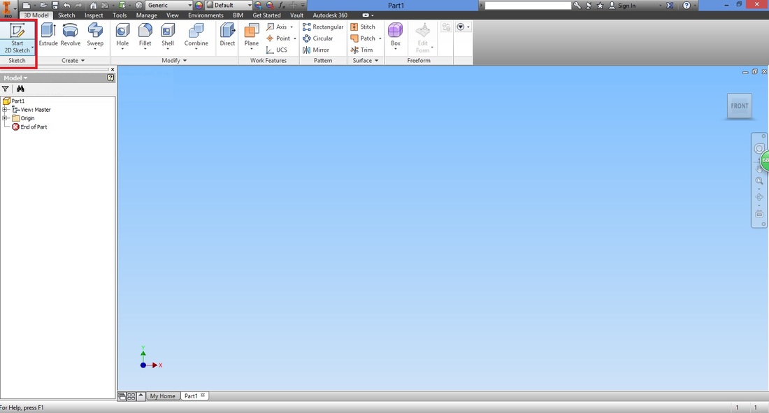
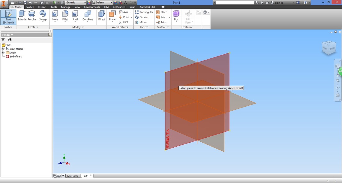
Next, select the plane you would want to draw on. Here I've selected the YZ Plane.
WHAT beginners SHOULD KNOW:
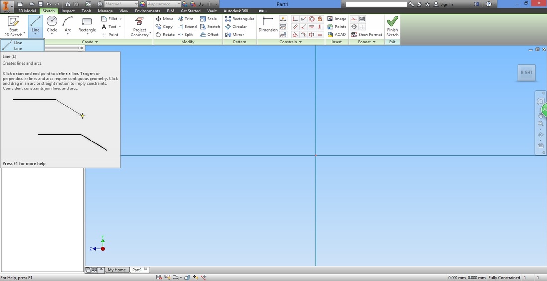
STEP 4From the Sketch ribbon, select the Line function.
Hover across the origin. The cursor will turn green and the X and Y coordinates are both zero.
Left click to start drawing line. 
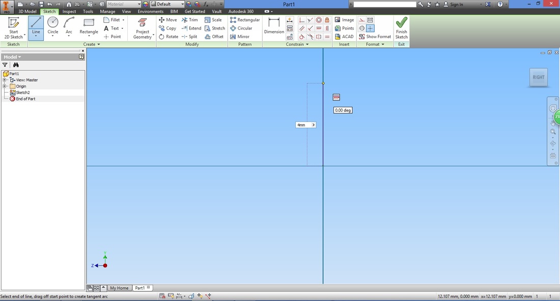
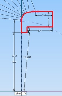
Input the distance and press "Enter"
Ignoring the curvature first, draw the remaining straight lines. (shown in sequence below)
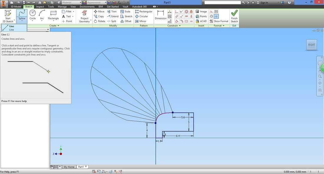
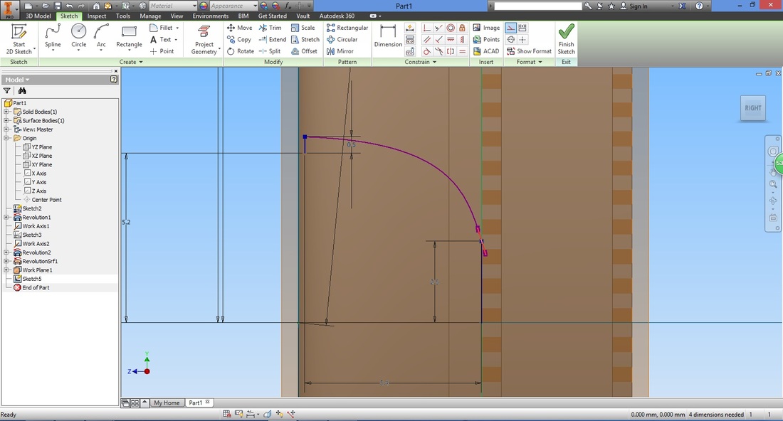
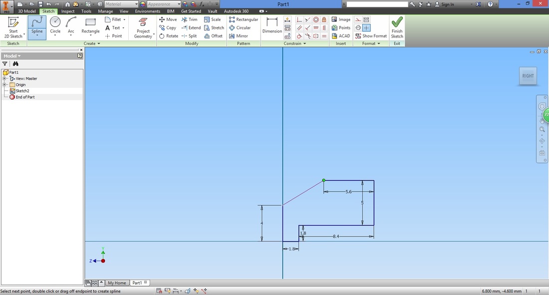
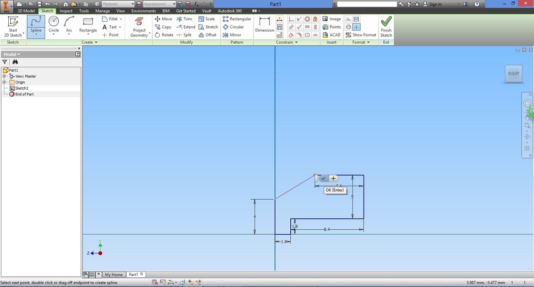
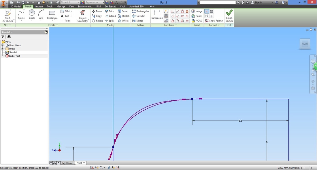
Select Spline (interpolation) function. This will allow you to draw a curve and stretch it as you desire (instead of using the arc function).
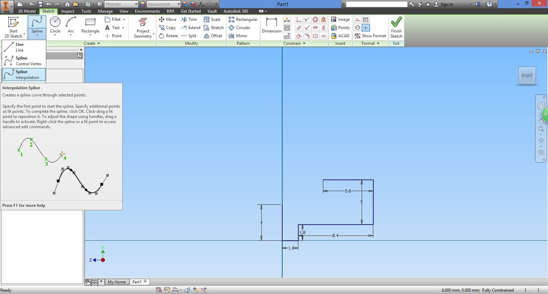
Select the start and end point which will close the gap resulting in a closed region.
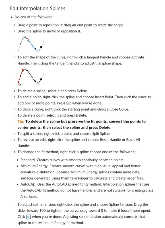
Right click near the end point of the line and select Activate Handle.
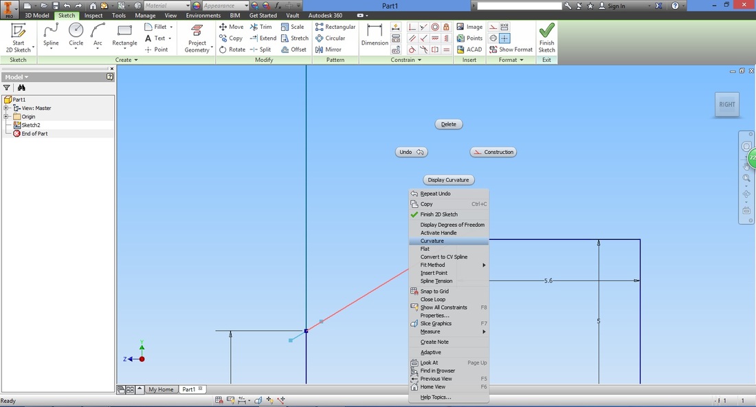
Activate Handle is right above the highlighted Curvature.
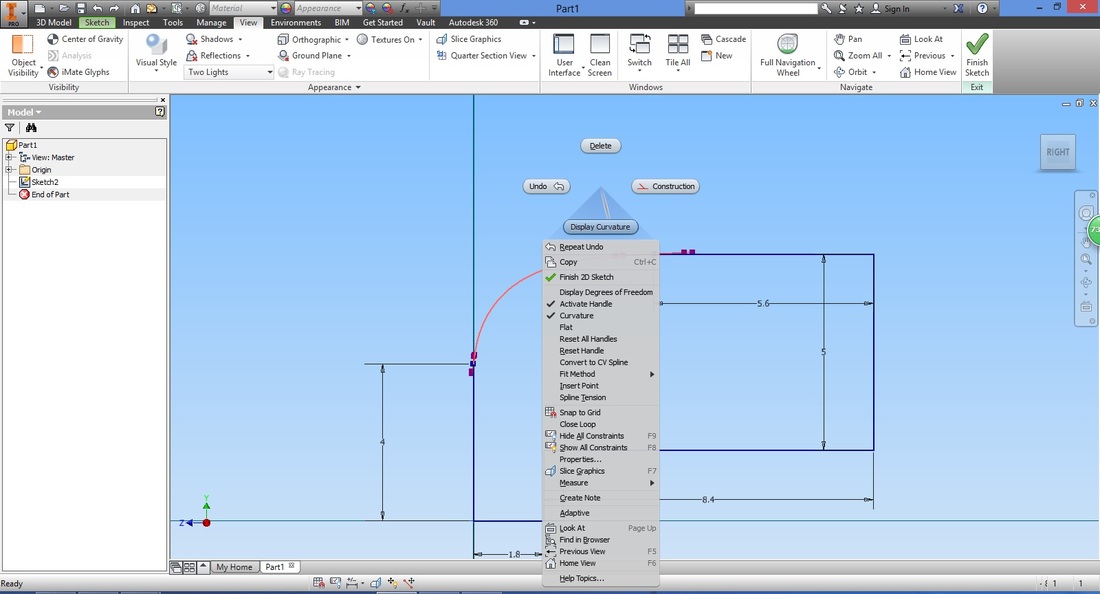
The additional line at the start and end points are called Tangent Handles. Use them by rotating/dragging to adjust the curvature.
Right click the line again, this time select Display Curvature.
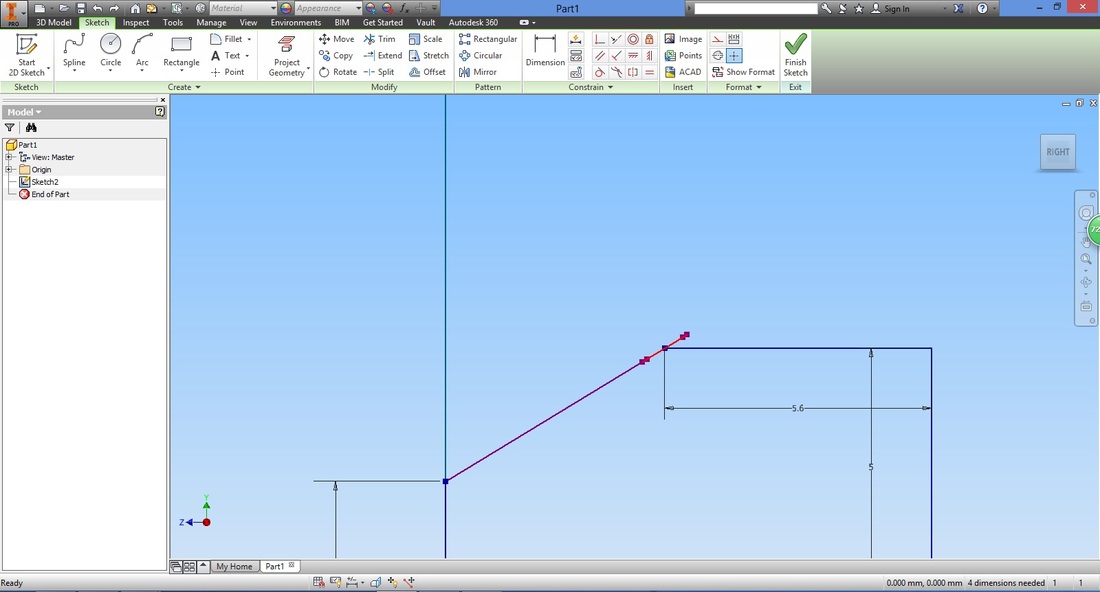
Adjust the Tangent Handles to achieve something like this.
Note that the curvature will affect the performance of the tyre/wheel. 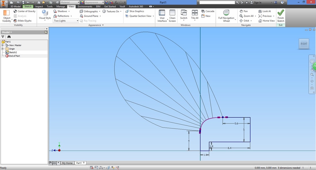
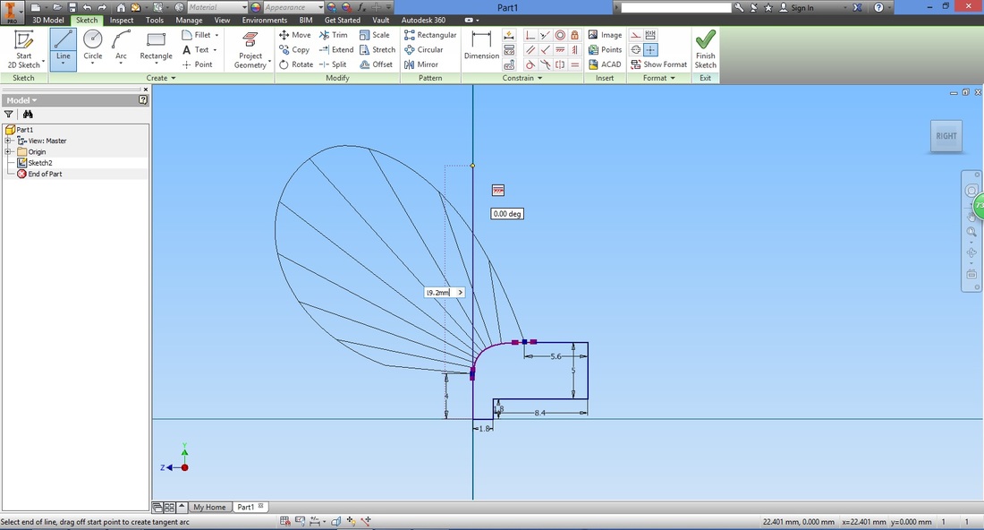
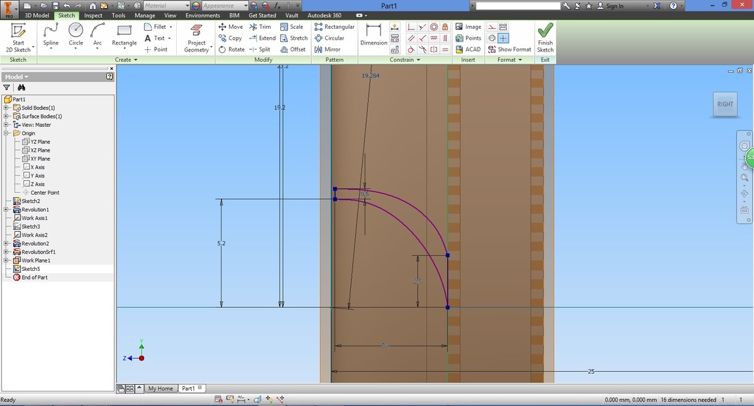
STEP 5Next we shift the closed region up. Select the Line function.
The start point is at the origin (left click origin). Input the desired distance (This will be the radius of the tyre).
Next, select the Move function.
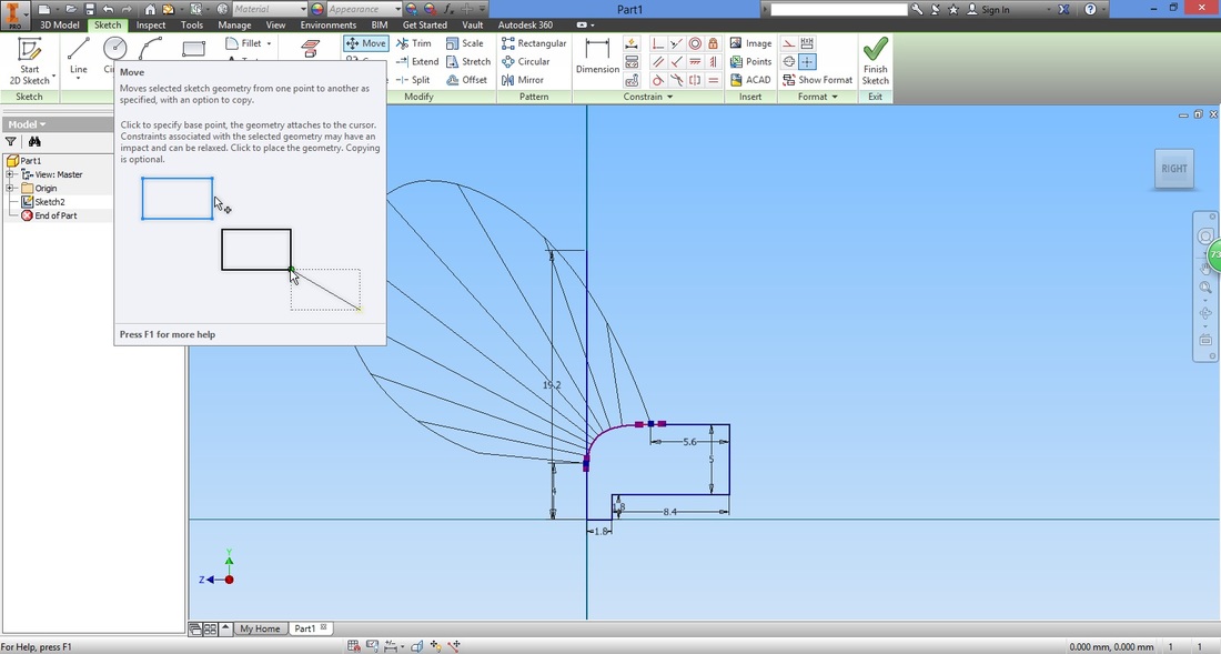
Select the closed region.
You can do so by
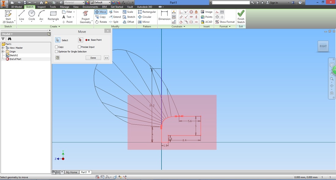
Select Base Point inside Move window. Left click the origin.
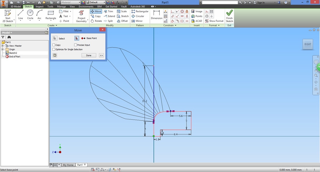
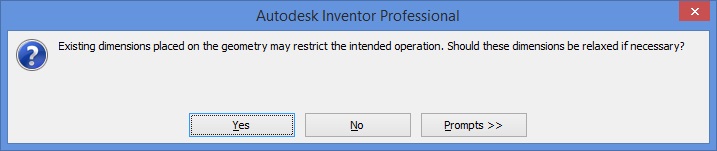
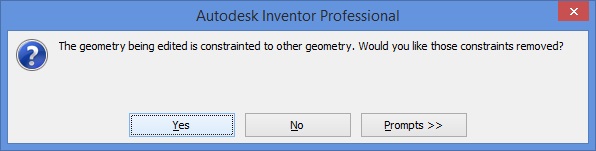
You will be prompted about the existing constraints. Select yes to overwrite them.
LEARNING POINT: Left click the end point of the vertical (radial) line drawn to shift it to the radial distance desired.
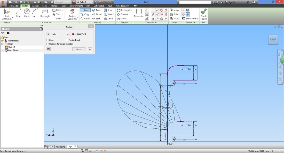
You will have something like this. Notice how the radial line did not move (as we did not select it).
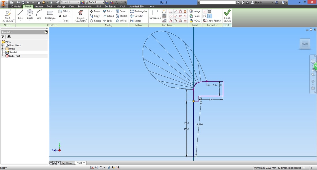
Tidy up by converting the radial line to a Construction line. This can be done by right clicking the respective line.

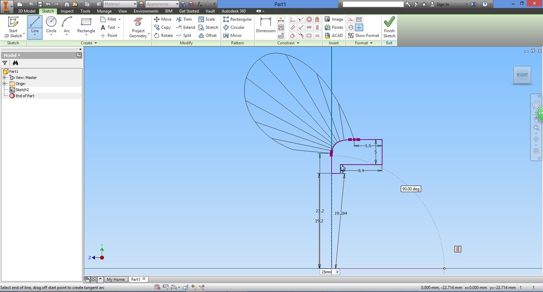
STEP 6Next we create a line that will be used as the axis. This is to enable you to use the revolution function later.
Select the Line function. 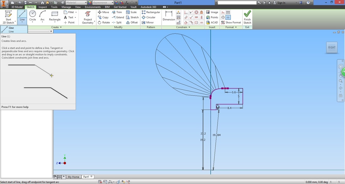
The length of this line does not matter. This is because, once it is converted to an axis, it will assume an infinite length. Ensure that this line is 90 degrees.
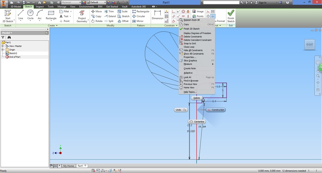
Convert this into a construction line as it is used for construction and not part of the component we are designing.
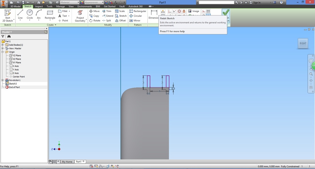
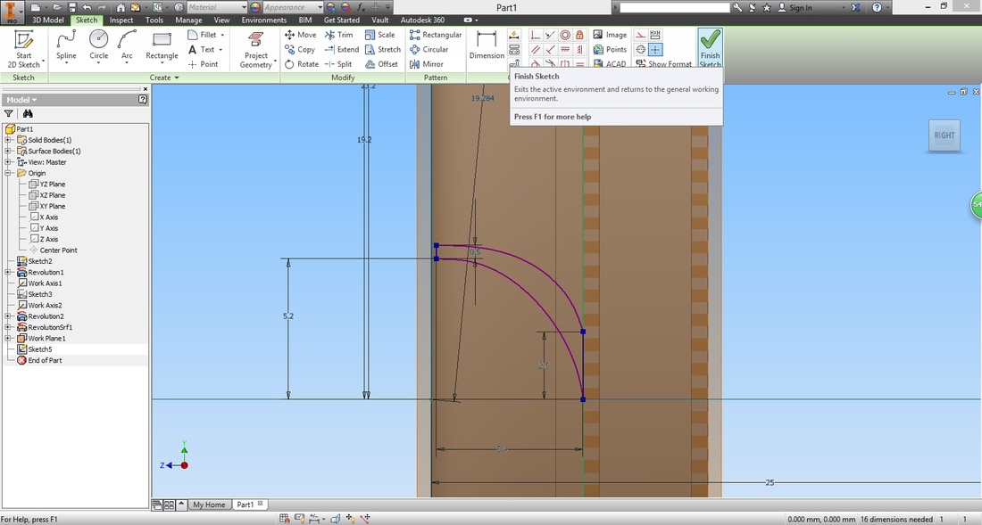
Once satisfied, select Finish Sketch to exit the sketch.
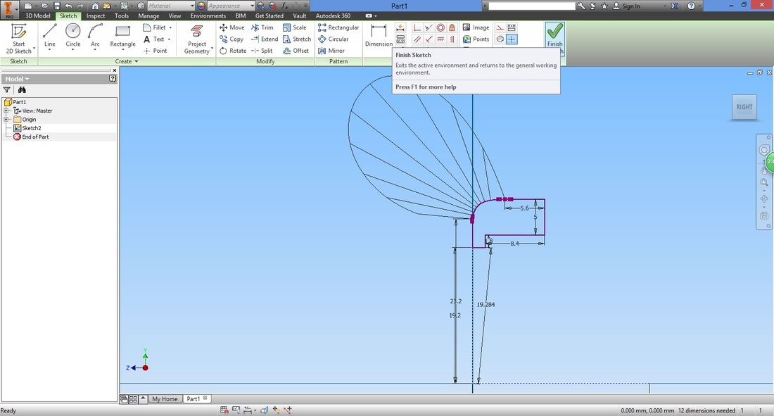
You will exit to the 3D view of the sketch.
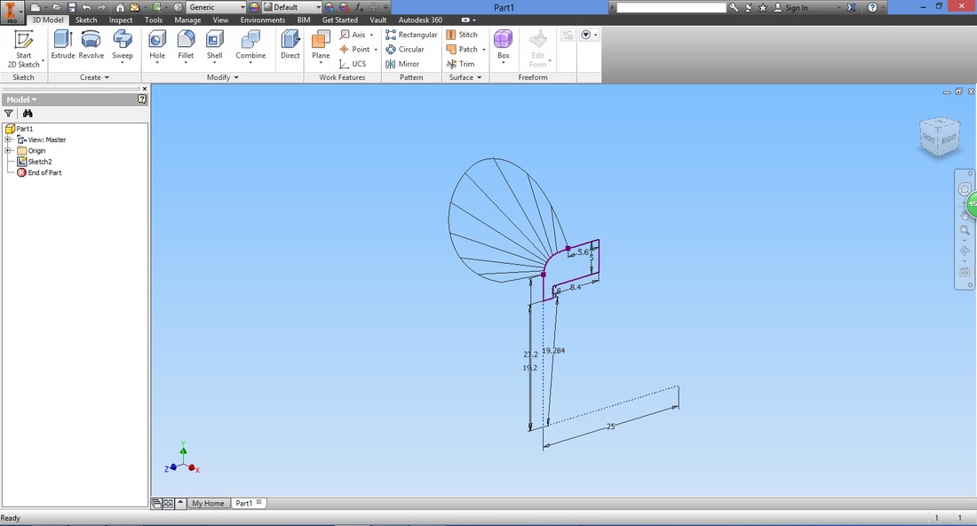
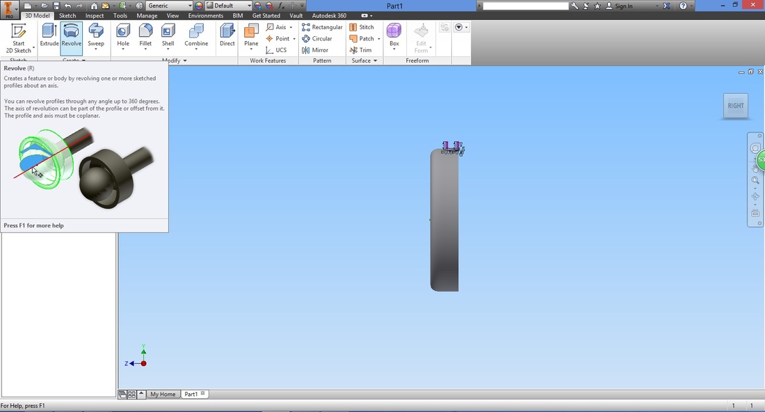
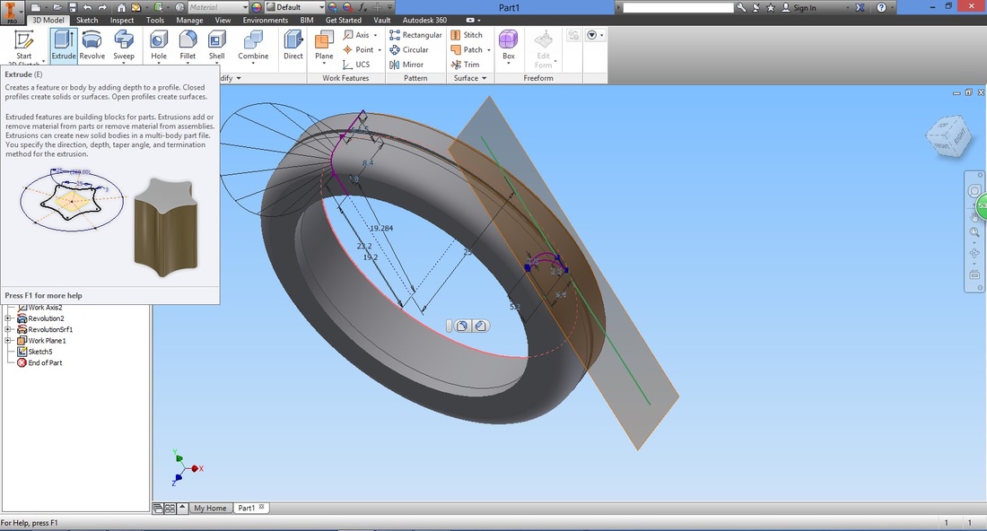
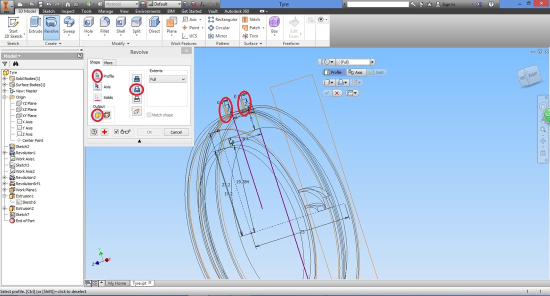
Step 7Select the Revolve function.
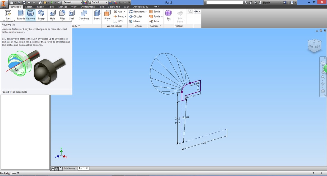
Select the profile to revolve.
Note that if the region draw is not a closed region, it is unable to have its profile selected. An open region occurs when there is a gap between points. 
Select the axis line drawn in the sketch.
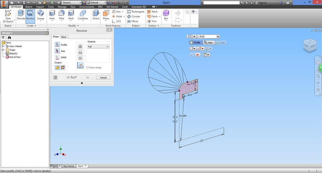
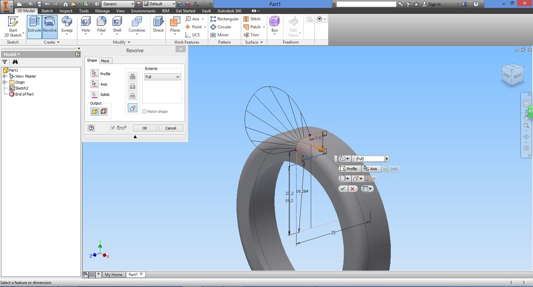
Configure the settings. Once the preview is correct, select OK to confirm.
step 8Next we create the gaps in the tyre.
Select to view the Right view, using the viewing box in the top right corner. 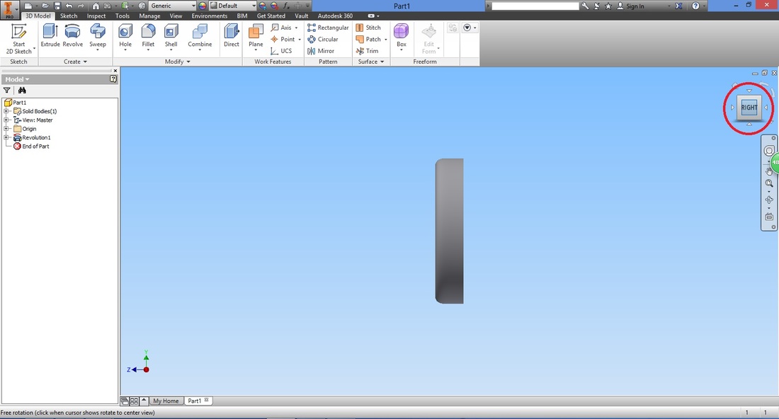
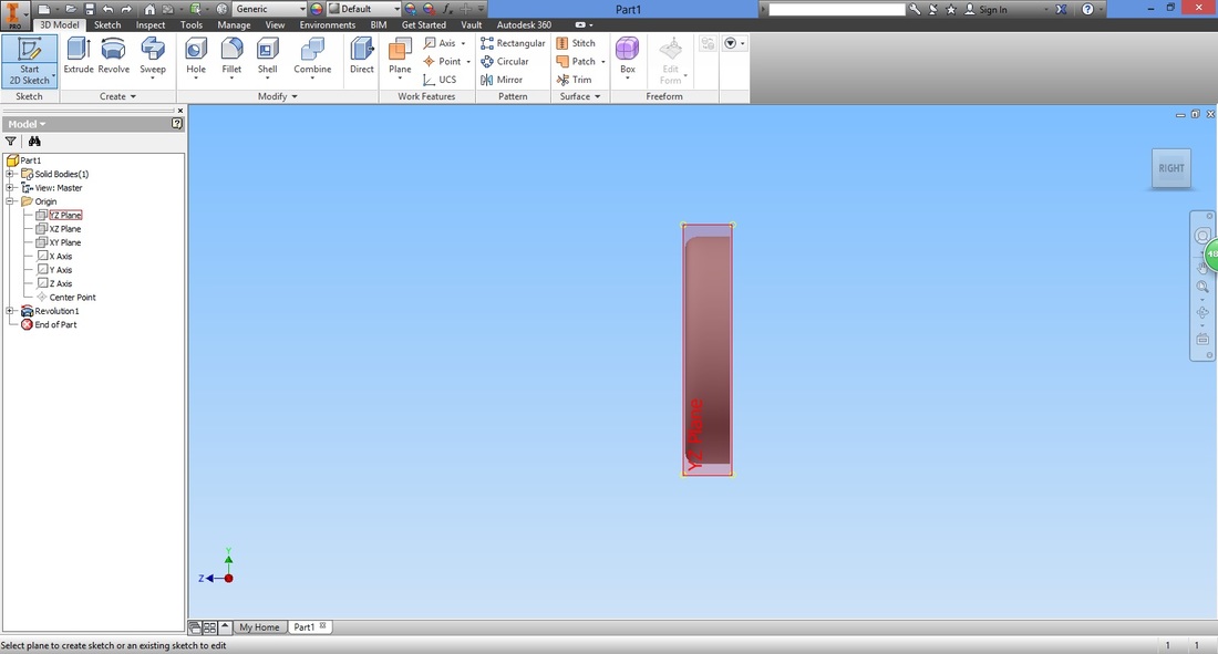
To create the gaps, we will sketch two rectangles and revolve them. Select the Start 2D Sketch function.

You will need to select the plane at which you intend to draw. If you observe the axis at the bottom left, you will realize that this plane should be the YZ plane.
To select the plane, expand the origin folder in the Model panel on the left. Select the YZ Plane.
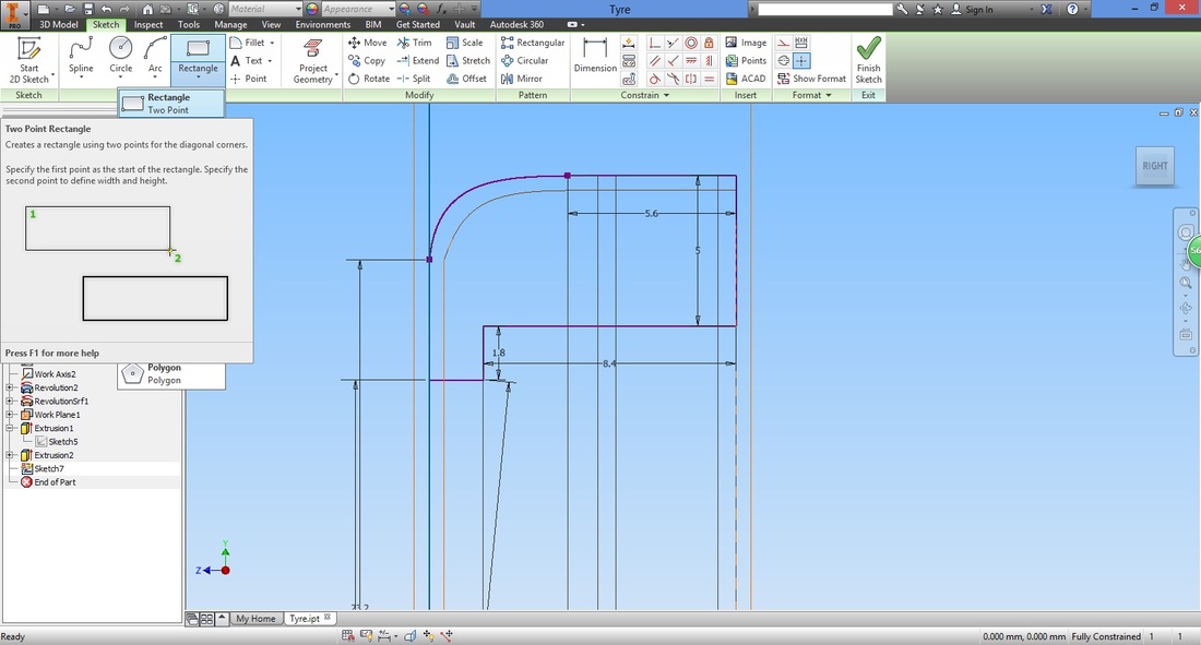
Select the Rectangle function to draw a rectangle.

Without selecting the left most line trace it, there will be a dotted line to guide you.
This is so that you create a line (or rectangle) along the line you have traced. 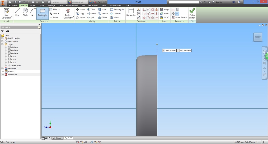
Key in the length, and without pressing Enter (or exiting) , key in the width.
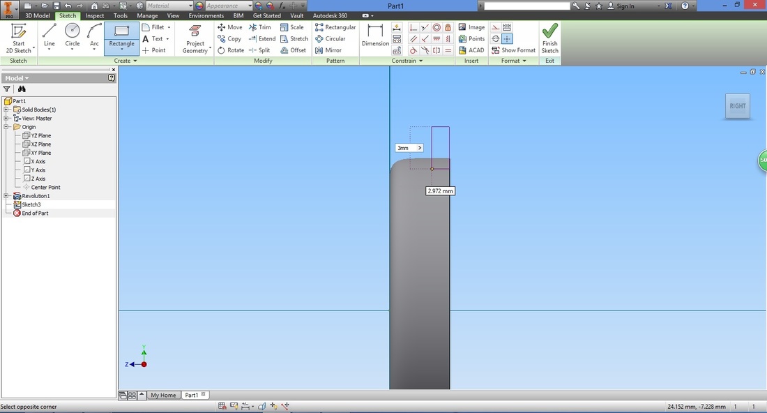
A rectangle will be formed as shown.
Select the Line function.
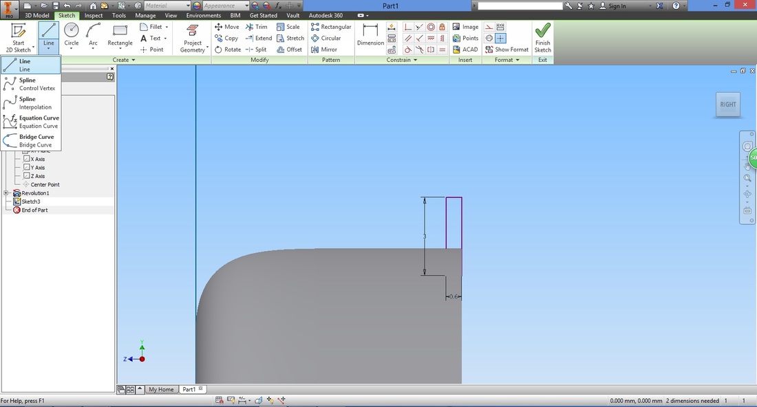
Hover around the corner of the revolved part and the horizontal line at the top will appear. You can then select the point (corner) as the start point.
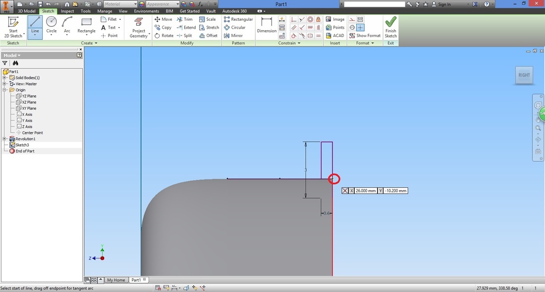

Input length
Once you exit the line sketch, notice the lines that appear during hovering have disappeared. This is because they function to only assist you when and where you requested (hovered).
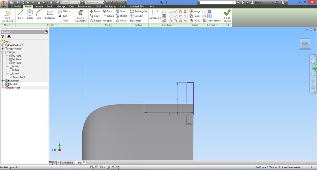
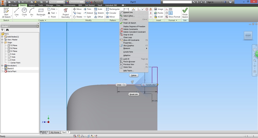
Convert this into a construction line.
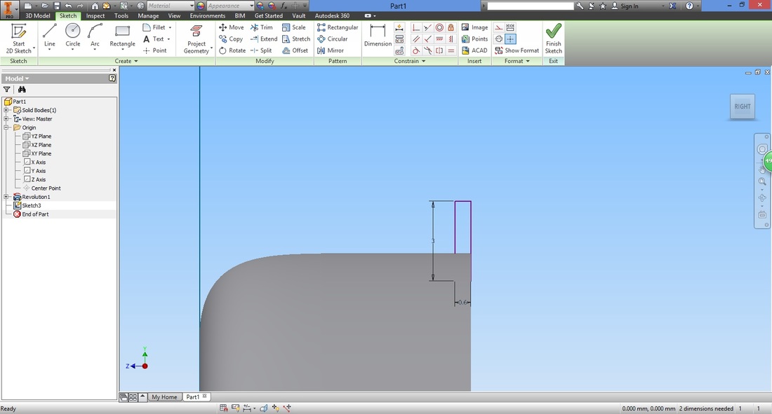
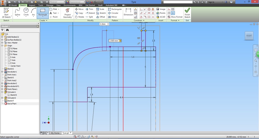
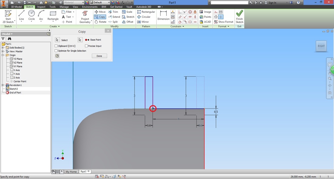
It's Such a hassle to tidy up. What happens if i don't? Before copying, use the Dimension function to dimension the distance of your first rectangle. This will allow you to adjust the depth of the gap.
Hover around the top of the revolution and a dotted line will appear. Left click it.
Next, select the bottom of the rectangle drawn.
Input the distance (depth of gap).
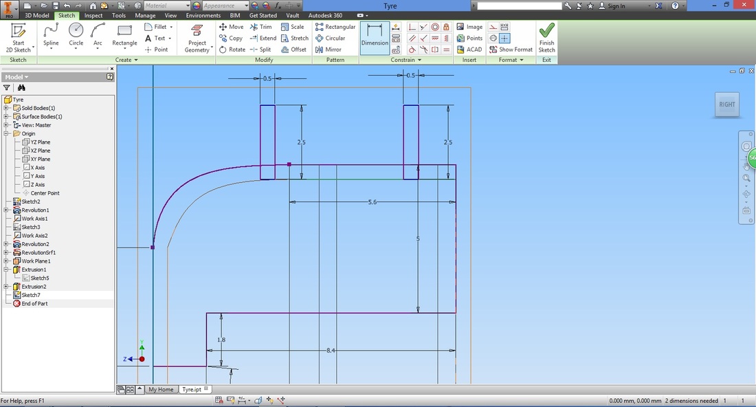
Select the Copy function.
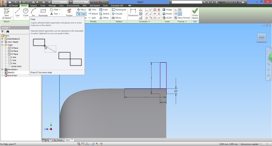
Select all the lines of the rectangle.
Recall that there are two methods to do so, as mentioned in Step 5. 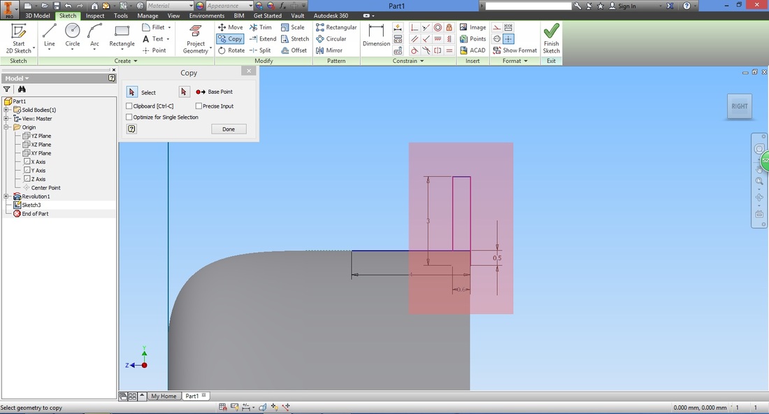
Next, select Base Point in the Copy window.
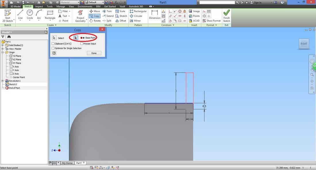
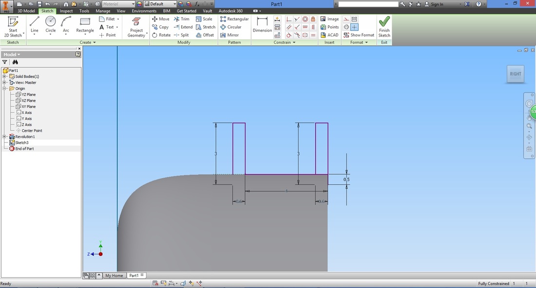
Select the start point of the construction line followed by the end point of the same line.
You will then have something like this.
Once completed, select Finish Sketch function to exit.
step 9This step will show you how to share a sketch so that it can be used for other functions.
Right-click the sketch in the Model panel and select Share Sketch. 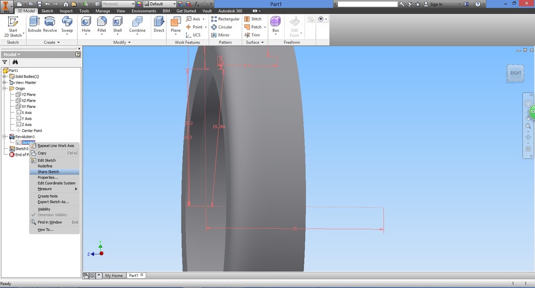
Now you can select the axis line in the first sketch and make it into an actual axis.
Select the Axis function followed by the axis line. 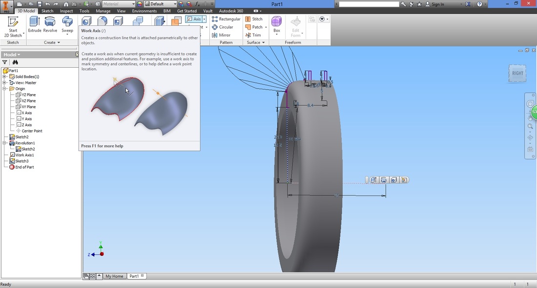
Axis function
Axis line in first sketch
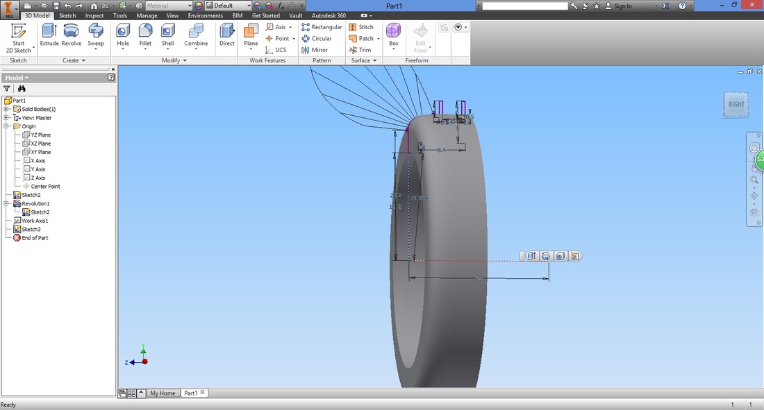
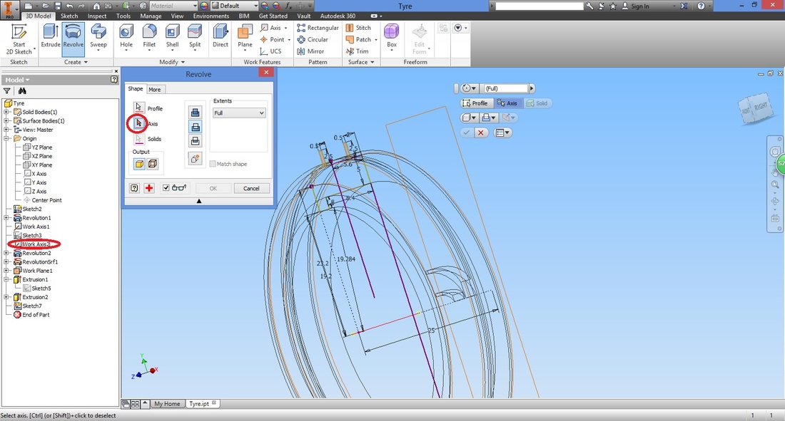
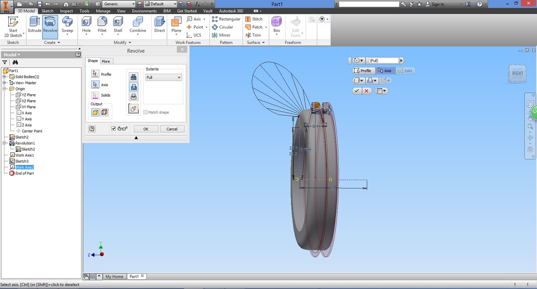
Could we have done this prior to step 7? Step 10Select the Revolve function.
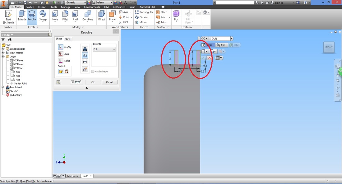
Ensure the cut type is selected in the Revolve window.
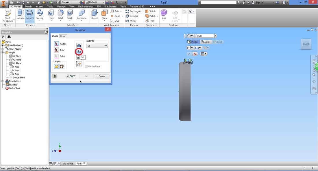
Select the profile (both the rectangles).
Select Axis in the Revolve window and then the axis created.
The preview will be shown. Once satisfied, select OK.
Step 11
Select the Offset from Plane function.
Here we create a plane to allow you to sketch at the tangent of the tyre. 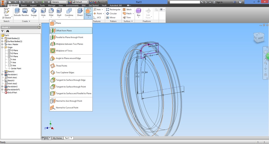
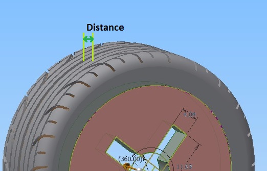
Select the plane we want to offset from-YZ Plane, and the distance we want to offset from the selected plane.
The distance here should be the radius of the tyre. 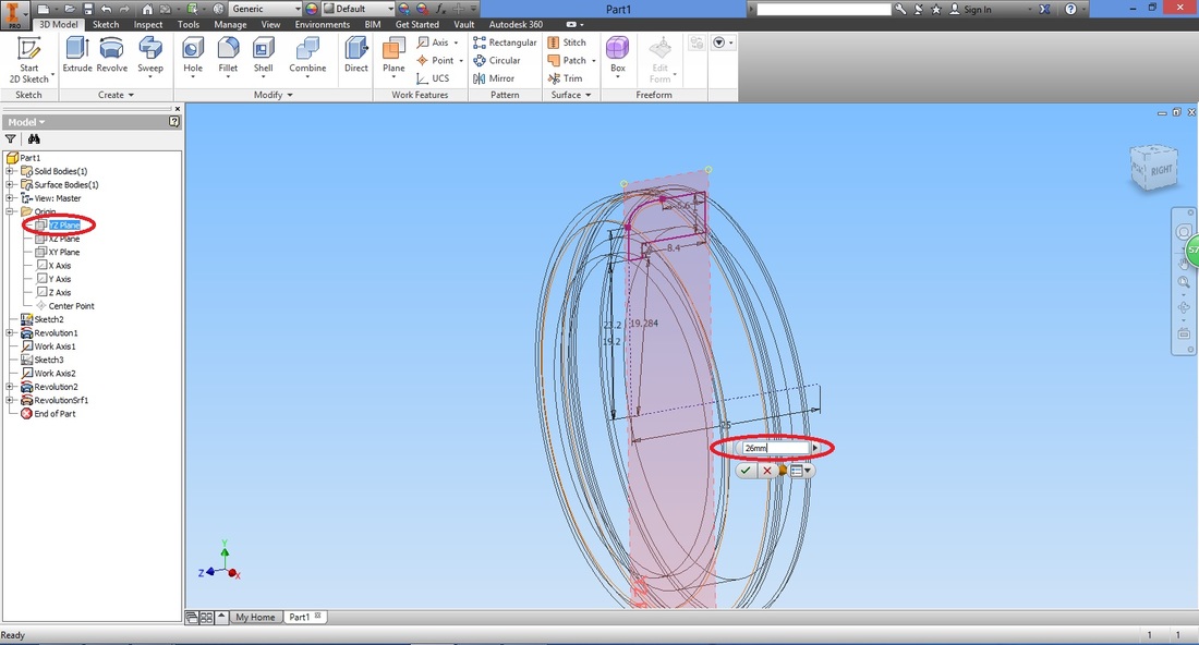
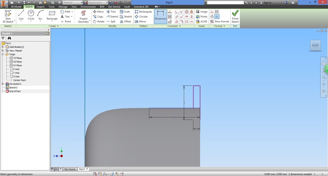
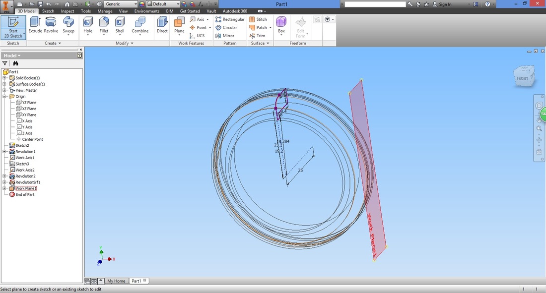
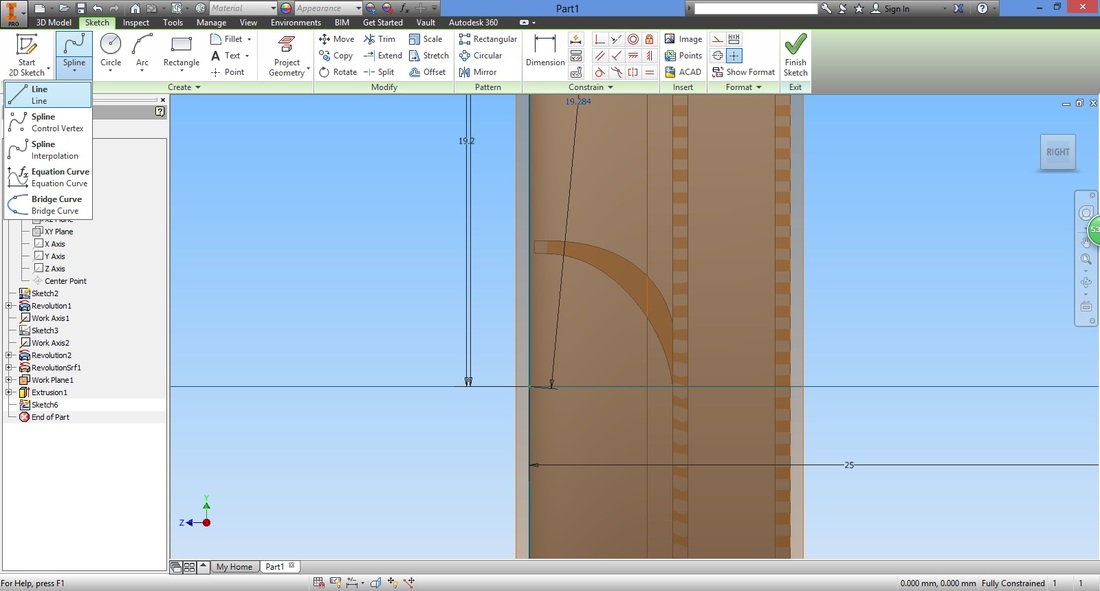
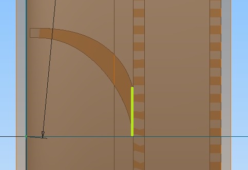
STEP 12Select the Sketch function to create sketch on the plane created.

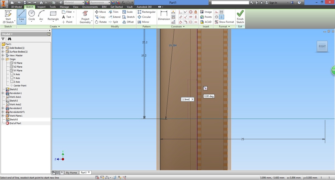
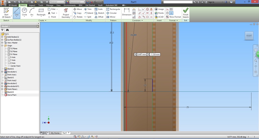
Draw the line vertically and input it's length. You can dimension it's distance from the first line subsequently.

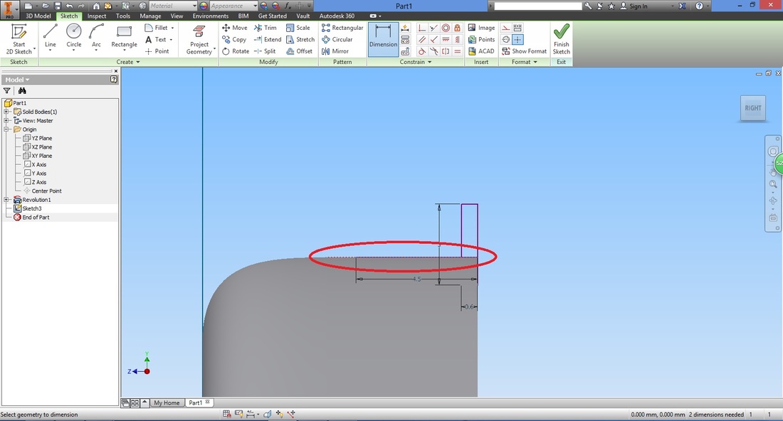
It's fun to have detailed and fine threads on the tyre, but consider your 3d printer capabilities if you will be 3d printing it. Select the Dimension function.
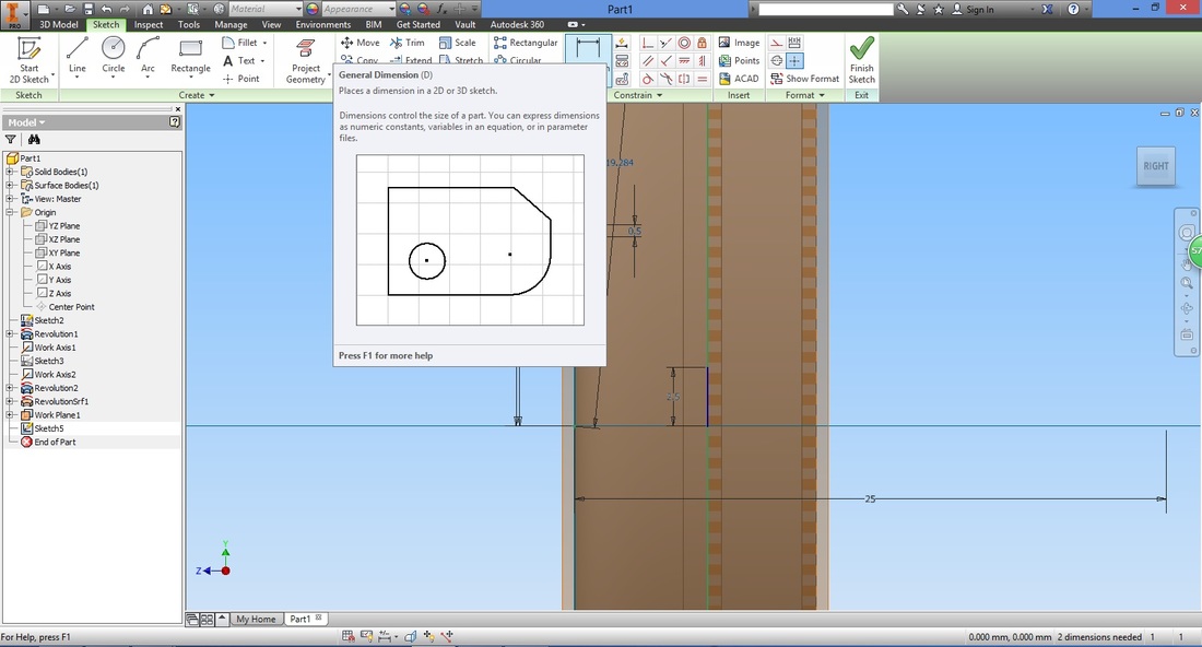
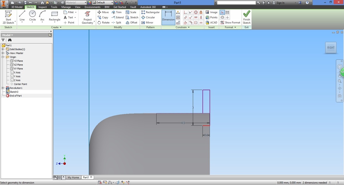
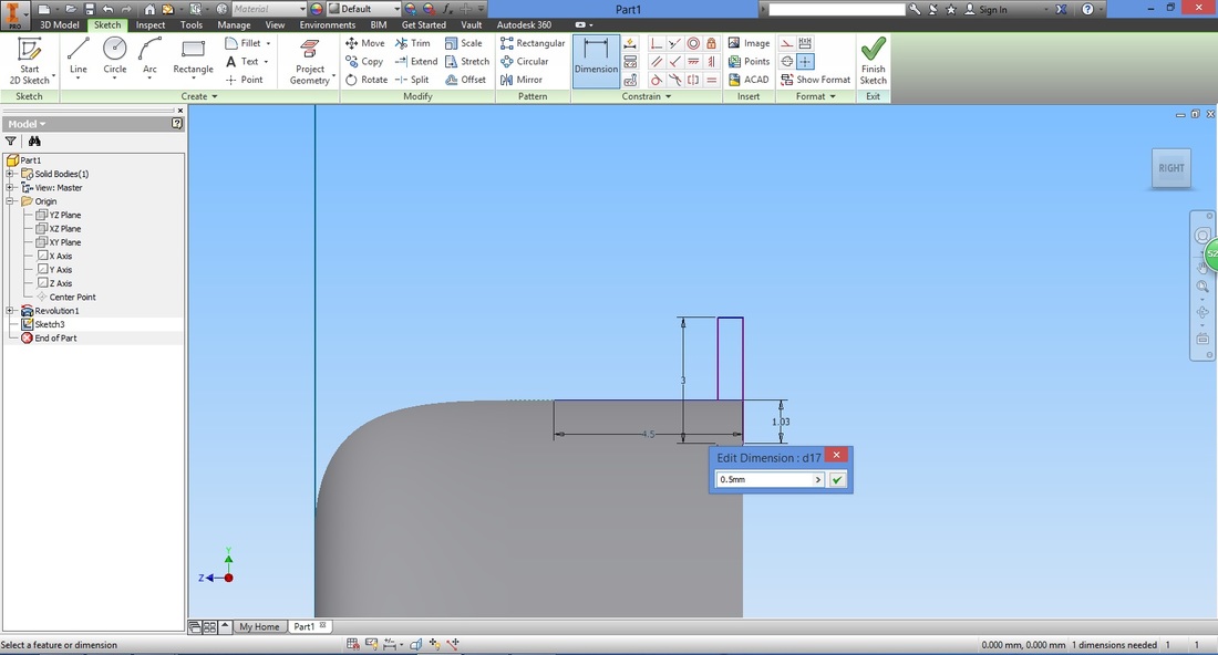
Select both the lines and input the distance between them.
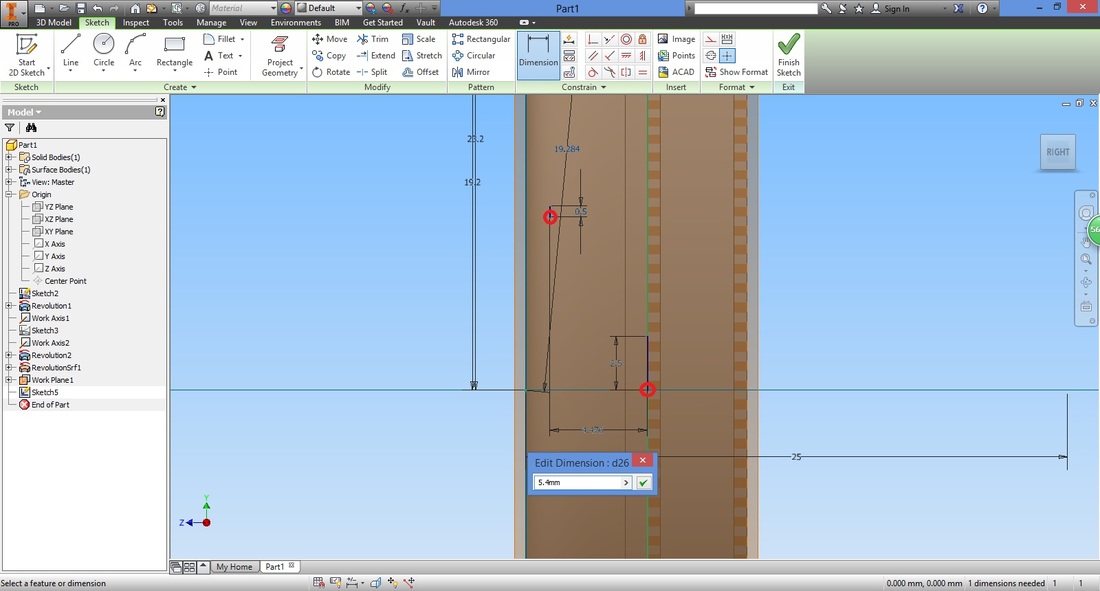
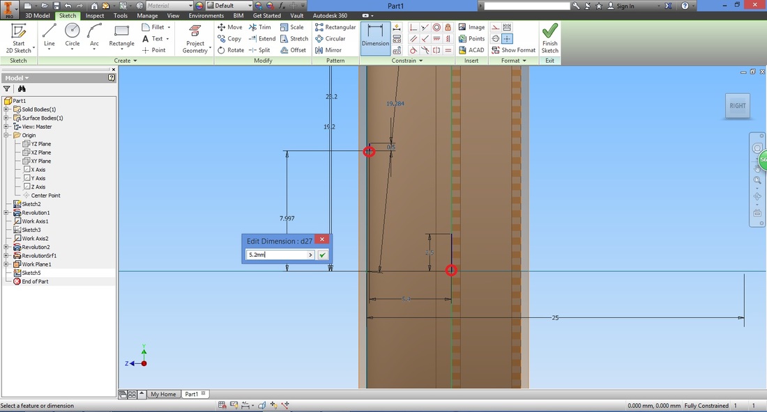
Select both lines again, this time pull the dimension horizontally by moving your cursor (where the pop up window is). Input the distance accordingly.
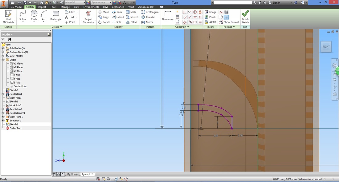
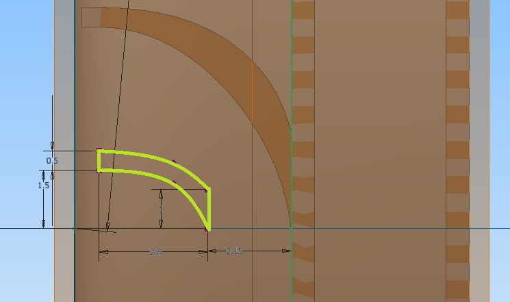
Select the Spline (interpolation) function.

The first spline should connect both top points together while the second spline connects the bottom points.
First/Top spline
You should have something like this.
Select Finish Sketch and exit.
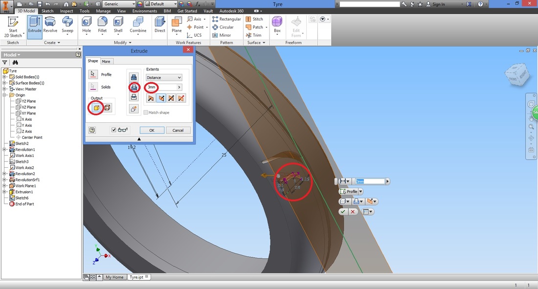
step 13Select the Extrude function.
Select the profile and using Cut type, extrude cut the sketch drawn.
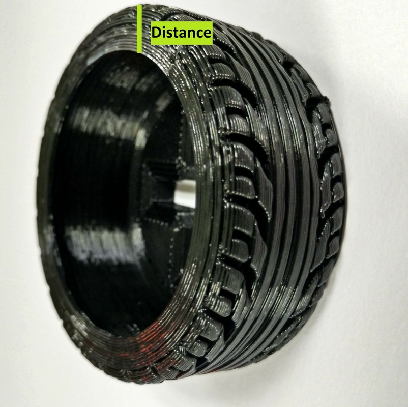
Here I've used distance of 3mm based on preference (it gives a pretty defined finish compared to other values I've tried). 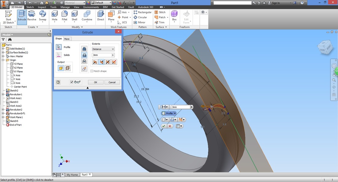
step 14Select Start 2D Sketch function and the Work Plane created.
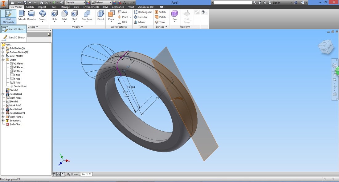
Select the Line function.
You will have something like this.
Exit the sketch (select Finish Sketch).


Similar to Step 13, select the Extrude function.
Select the profile and configure the settings accordingly.
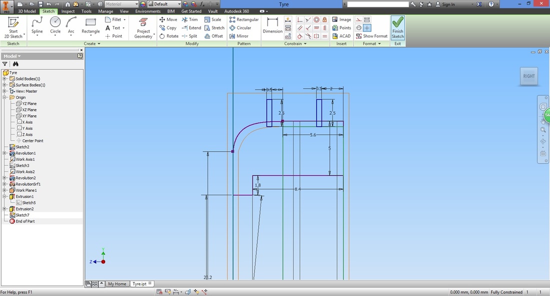
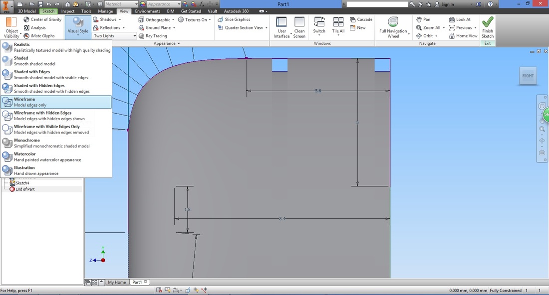
step 15Here we start another Sketch using the same plane.
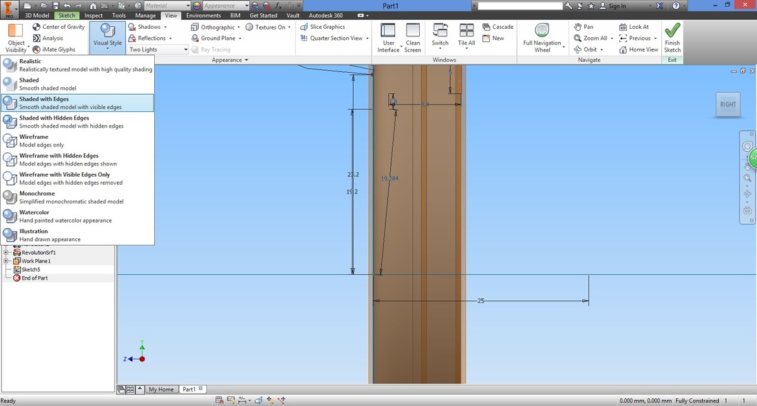
1. Why are we constantly using the same plane? Can't we do it all in one sketch? 2. IF ALL SKETCHES WERE DONE ON THE SAME PLANE, AND YOU NEEDED TO SHIFT ONLY ONE PART OF THE SKETCH TO A DIFFERENT PLANE, WHAT WILL HAPPEN? 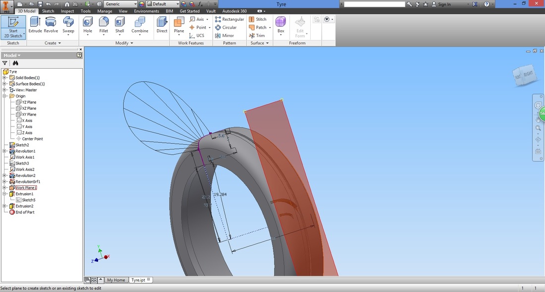
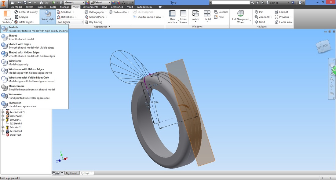
To ease viewing, convert the part into a Wireframe visual.
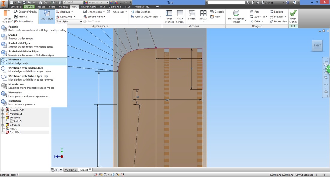
Select the Rectangle function.
*similar to Step 8
Create the rectangle as shown. It's height does not matter as we would only need to prioritize the depth and width of the gap. 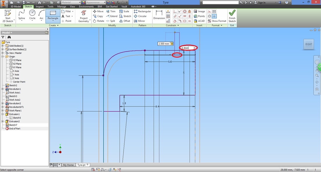
Draw another rectangle.
Select the Dimension function and adjust the depth of both gaps.
Exit the sketch.
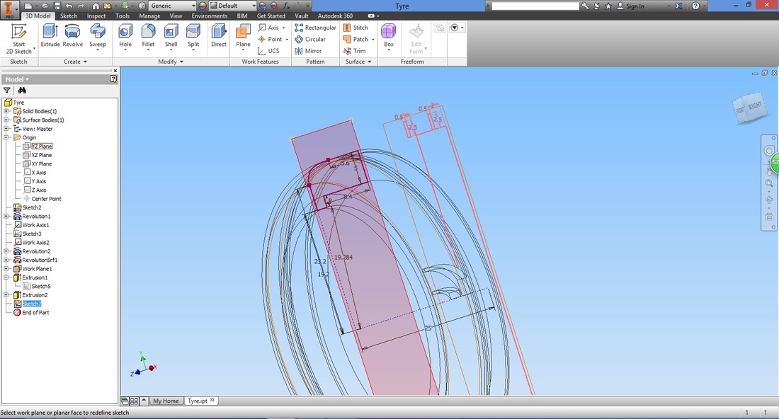
As mentioned earlier, this sketch was drawn on the wrong plane. If you were to revolve this, the cut would not be accurate.
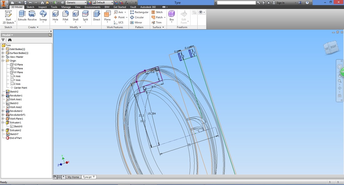
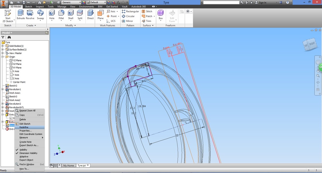
Right click the Sketch and select Redefine.
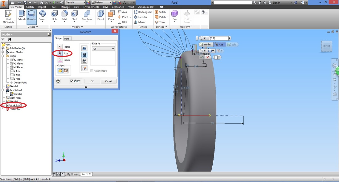
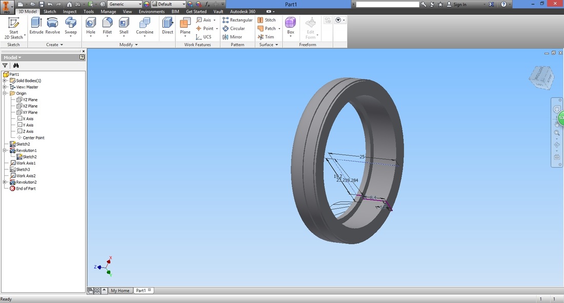
step 16You can now create the gaps. Select the Revolve function.
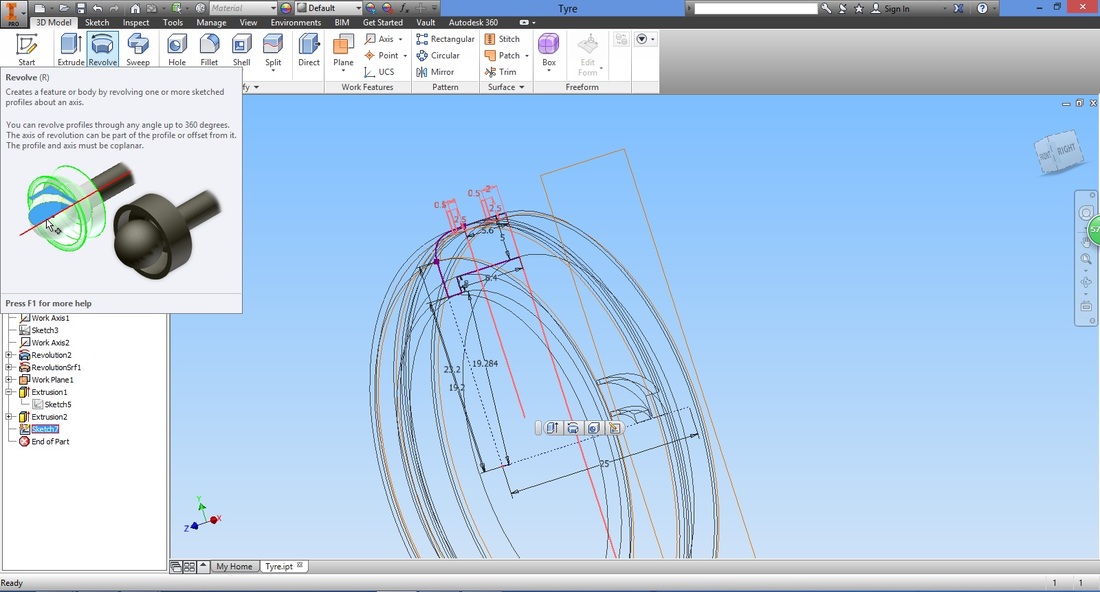
Select the profile and cut type.
Select Axis in the Revolve window and the axis created.
By changing the view, you can view the gaps created more clearly.
Step 17
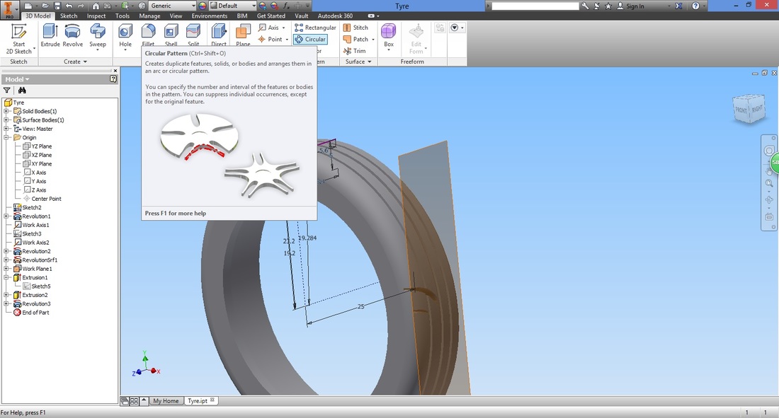
Select features to copy.
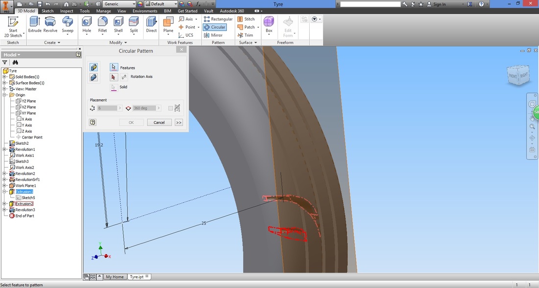
Select the Rotation Axis in the Circular Pattern window and then the work axis.
Configure the settings. 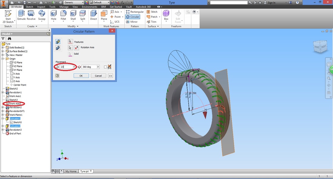
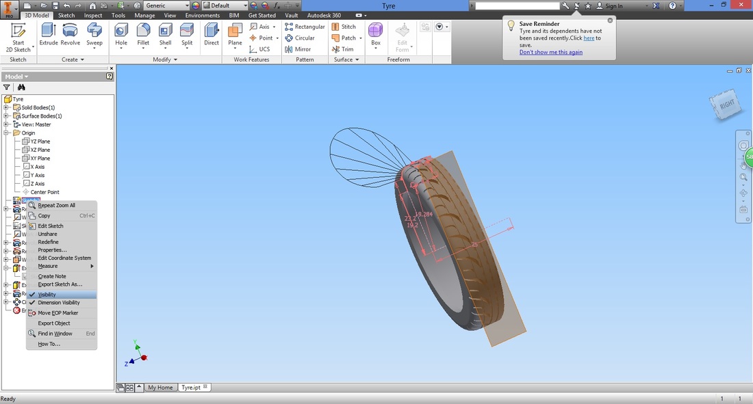
If you find it inconvenient to have the first sketch visible, simply right-click it and un-check Visibility.
Step 18Now, we mirror the part to have the complete tyre.
First, create the mirror plane. Select Offset from Plane function. 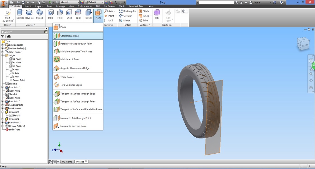
Select the face shown and let the offset be 0mm.
This means the plane created will be on the face selected. 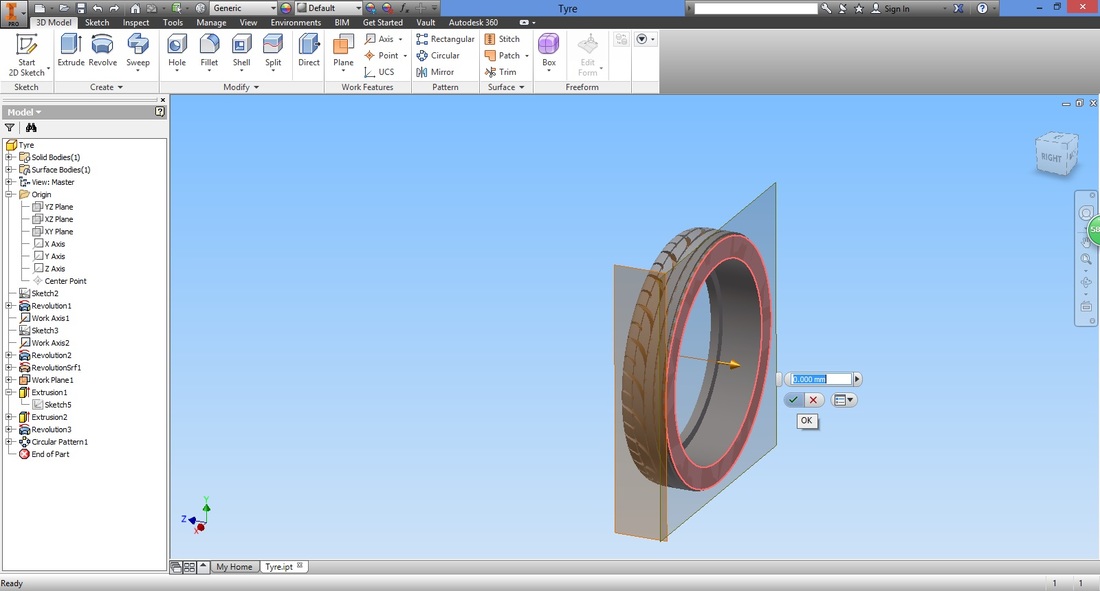
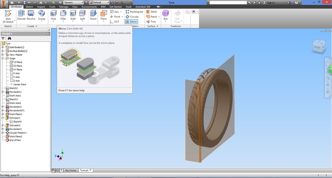
Select the Mirror function.
Select all the features we want to mirror.
You may refer to the highlighted features in the Model panel (on the left) to ensure all the necessary parts have been selected. 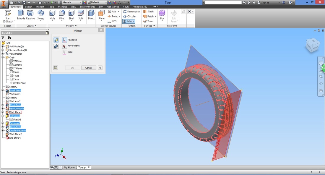
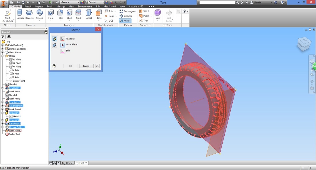
Select the Mirror Plane in the Mirror function and the plane created.
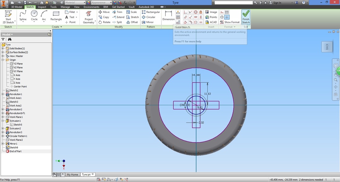
STEp 19
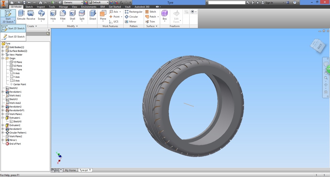
You can select the face you wish to sketch on. It can be on either side of the wheel.
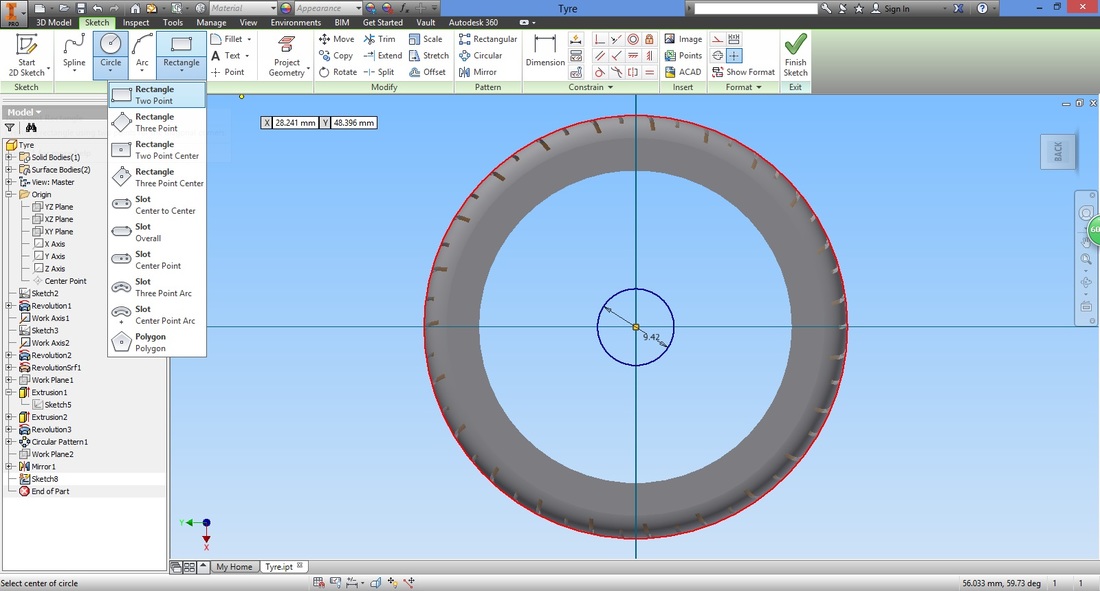
Select the Circle function.
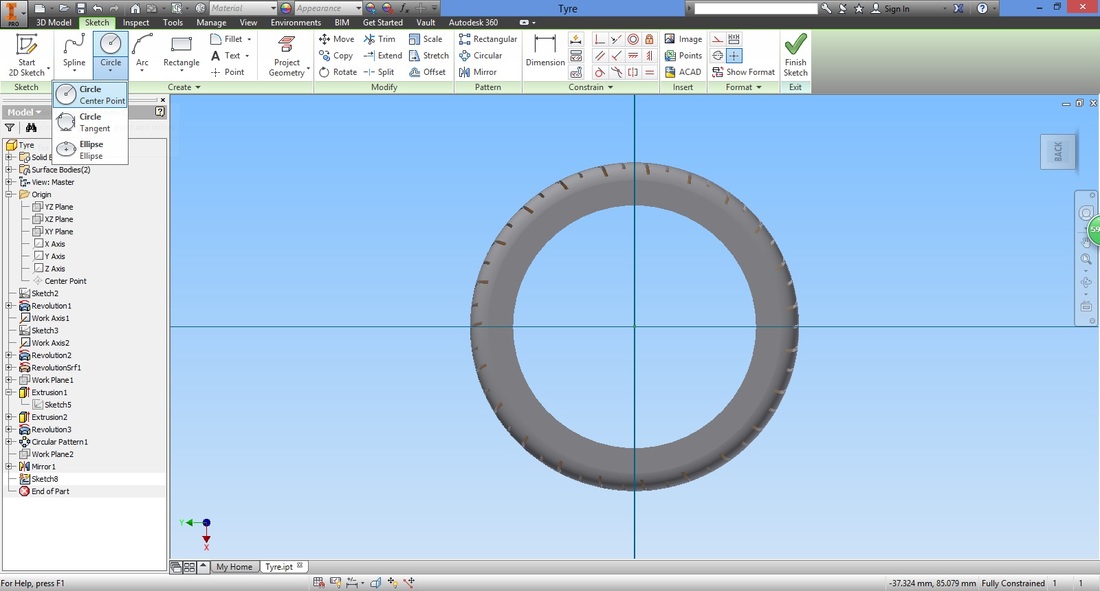
Select the origin as the centre of circle.
Input it's diameter. 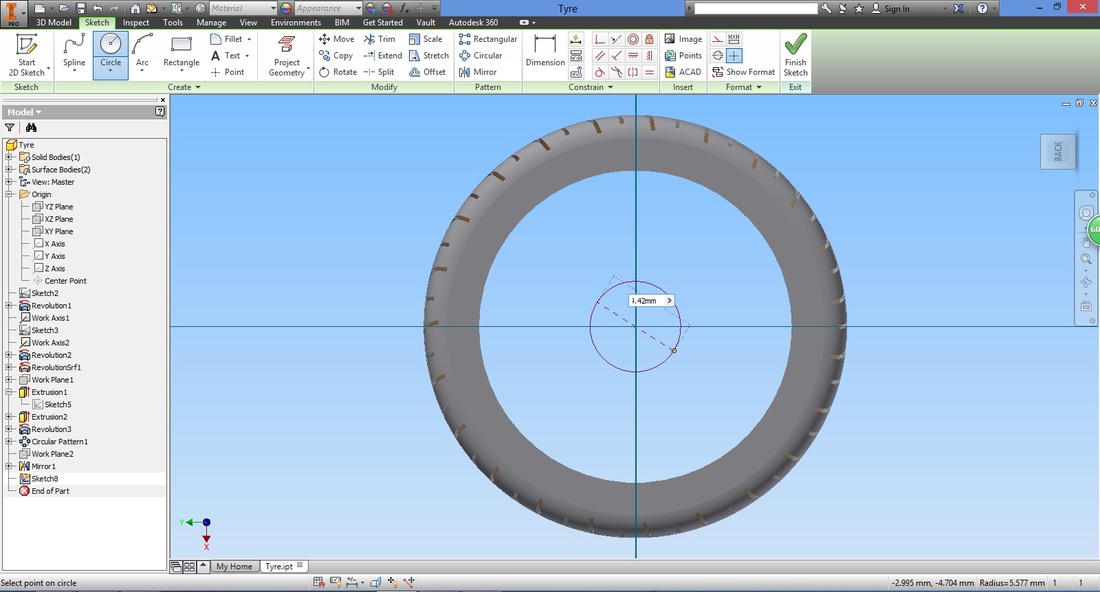
Select the Rectangle function.
Input the rectangle length and width accordingly.
(Recall: After inputting the first dimension, left click the other input without pressing Enter or exiting in between.) 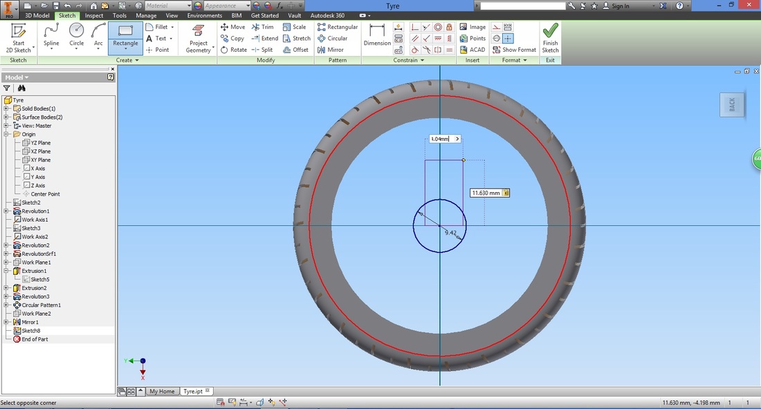
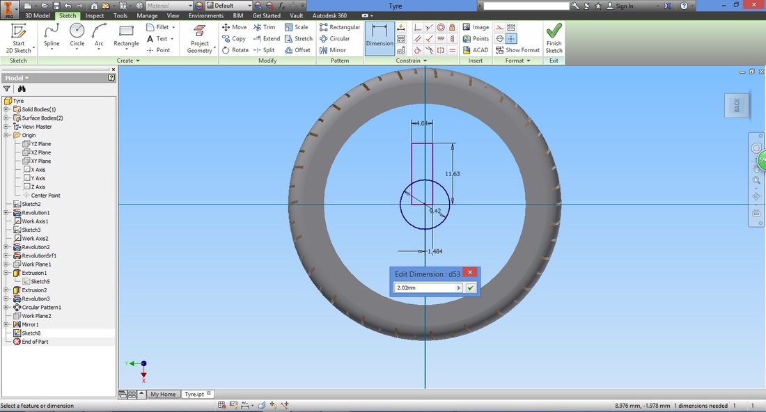
Select the Dimension function.
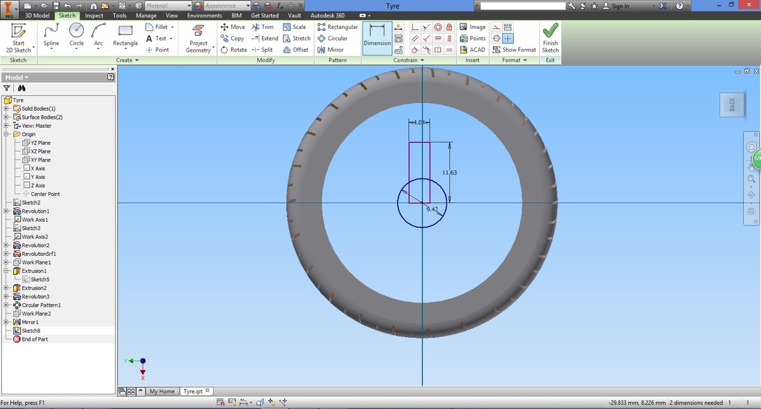
Adjust the midpoint of the rectangle to the origin.
Select the Circular Pattern function (note that this is similar to the Circular Pattern function under the 3D model ribbon, but for 2D sketches).
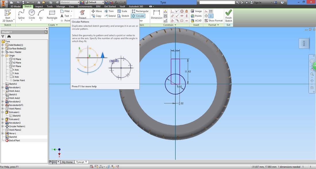
Select the rectangle as the Geometry to copy.
Select Axis in the Circular Pattern window and select the origin. Configure the settings. (Note that the no. of patterns to create includes the original.) 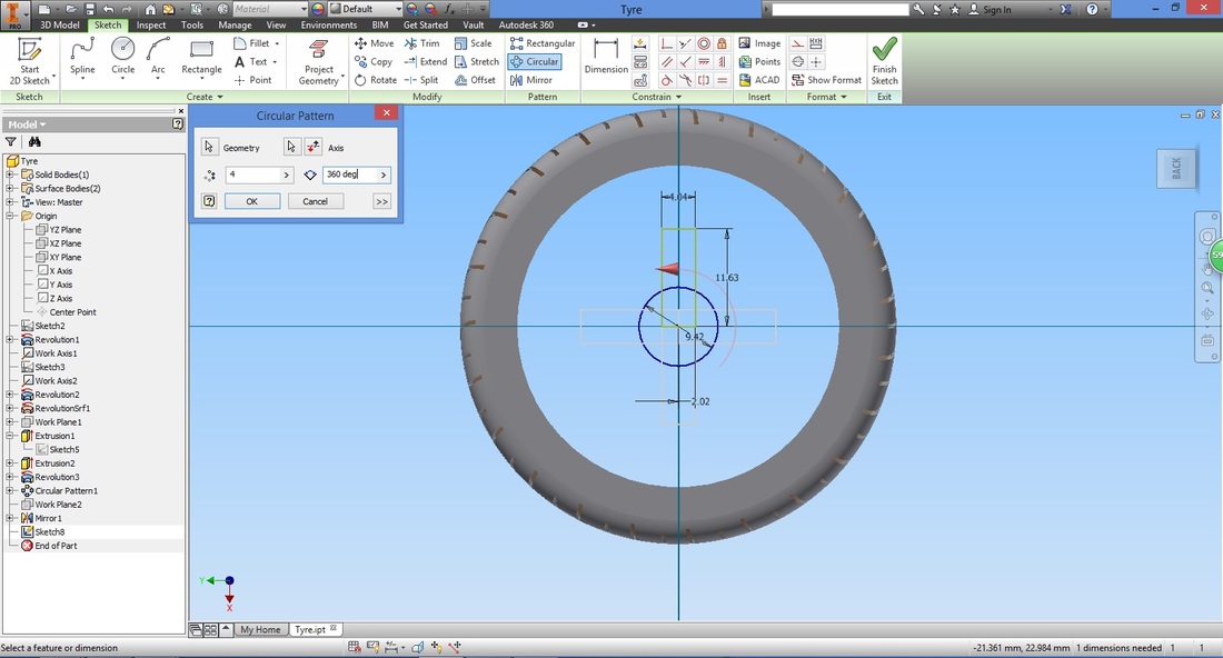
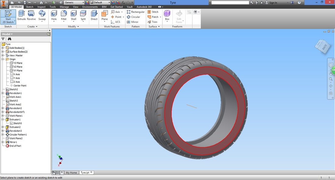
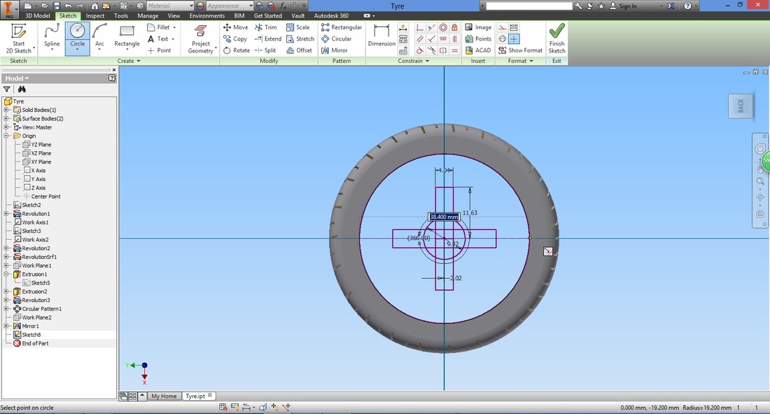
Select the Circle function.
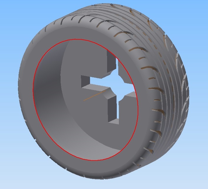
We are going to trace the inner rim of the tyre. WHy? 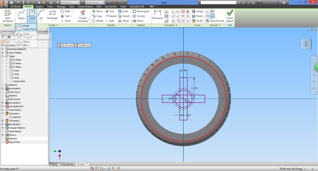
Select the inner rim (You can double check by checking the diameter.)
Once done, exit the sketch.
Step 20Select the Extrude function.
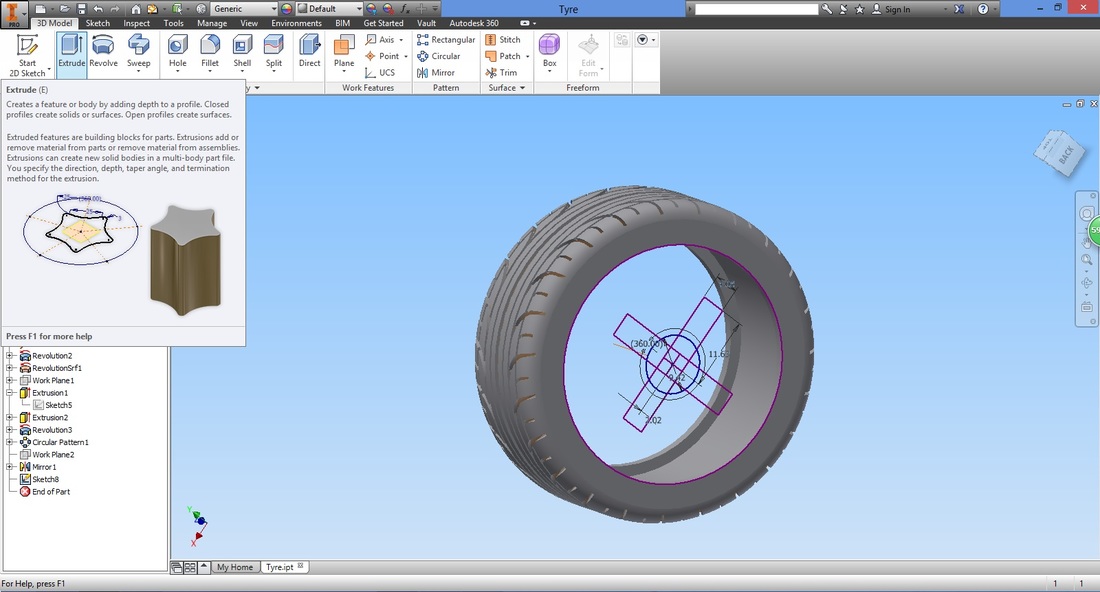
Select the profile to extrude. It should be in Join type operation (not Cut).
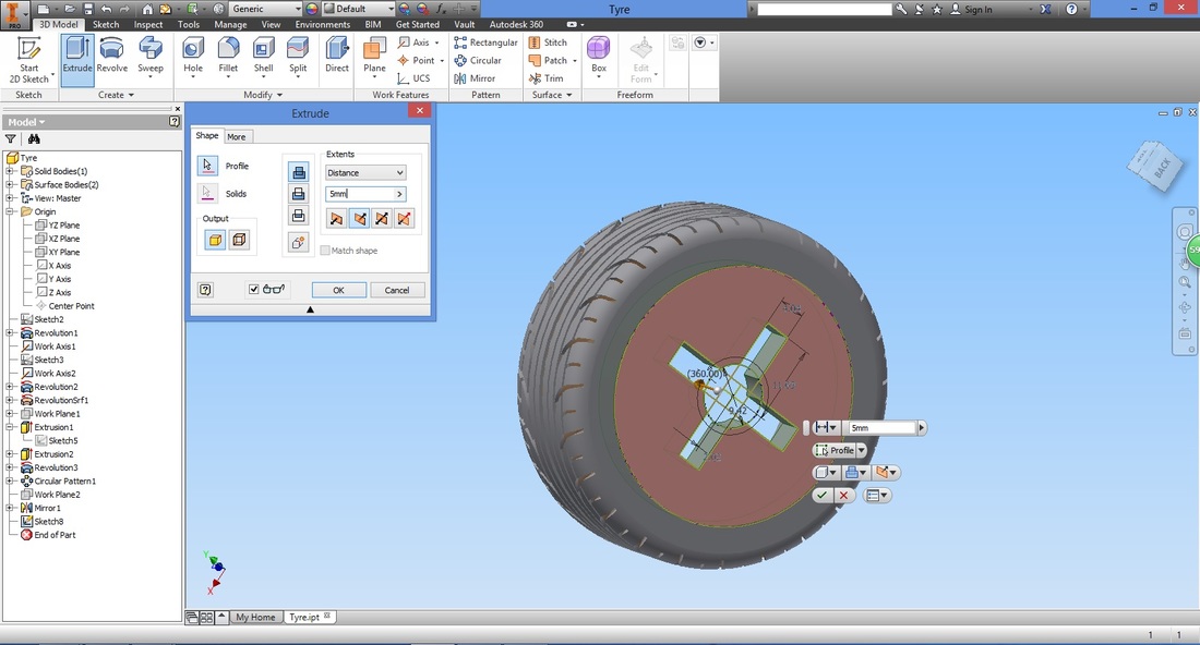
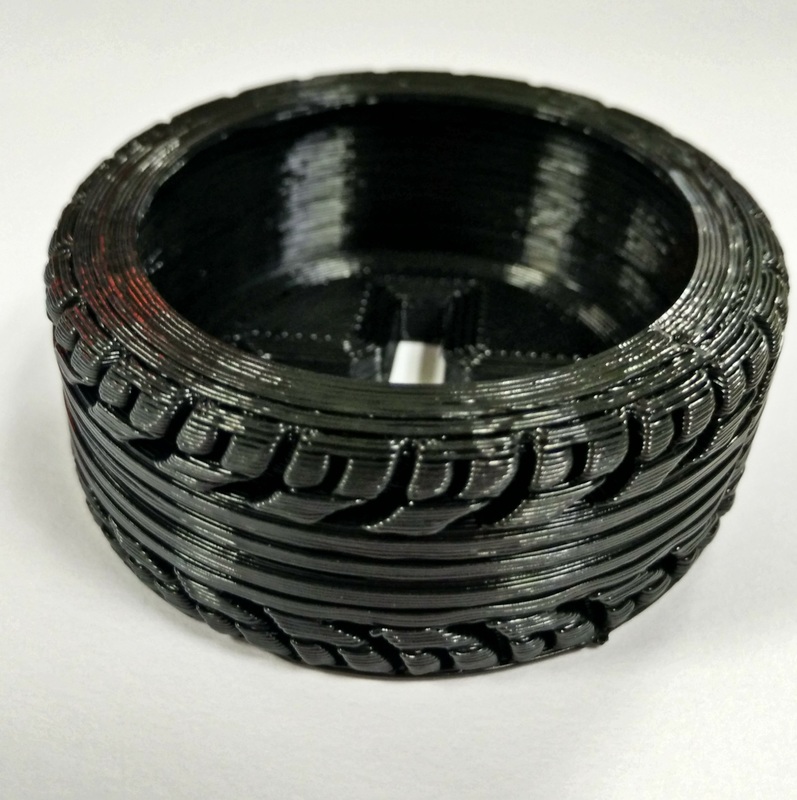
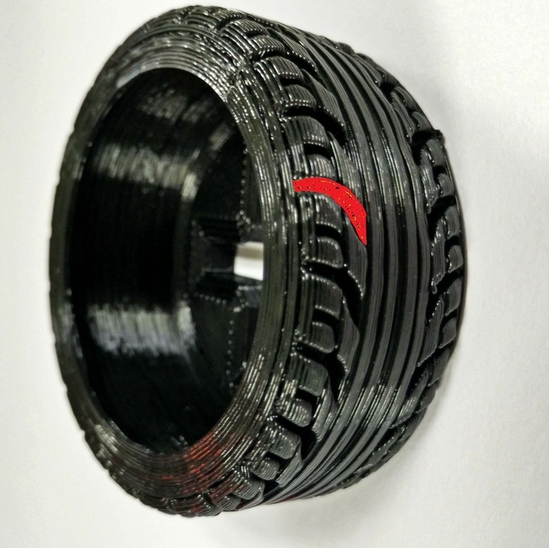
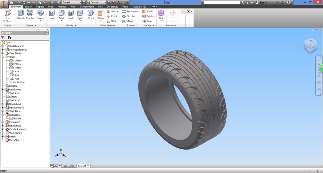
You will hence, have the following.
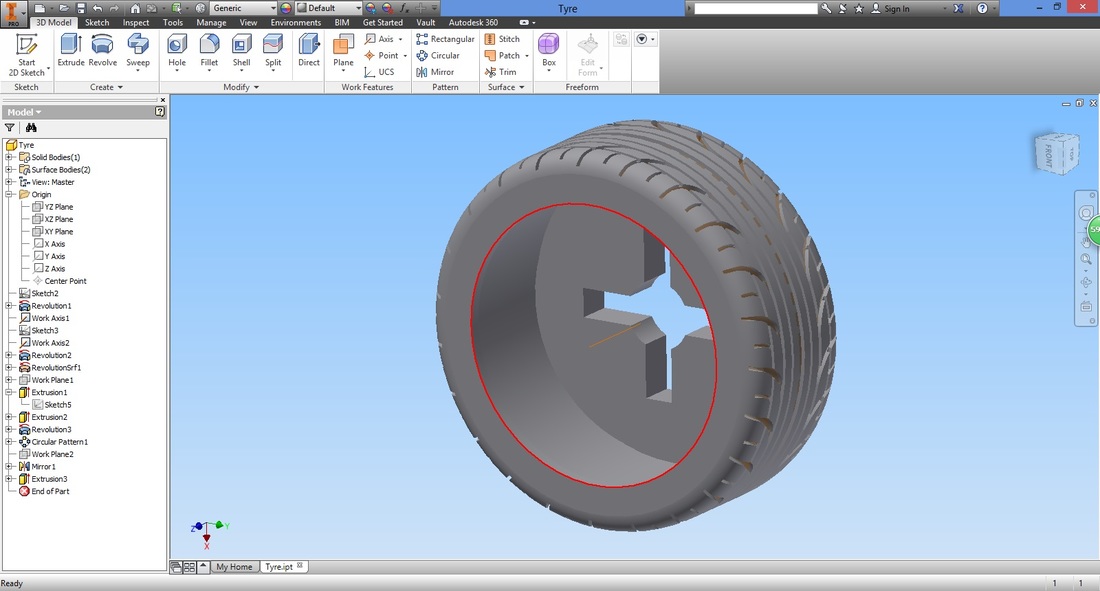
CONGRATULATIONS!
| ||||||||||||||||||||||||||||||||||||||||||


Download Tyre file |
| ||
REFERENCE LINK
- SolidWorks tutorial: modeling a tire by Klaus Falk Hansen
https://www.youtube.com/watch?v=9hZuixuIveM
